Introduction to Arduino
Arduino is one of the most popular microcontroller ICs for electronic projects. It is an open-source, programmable electronic component. It is made of a physical hardware that can be programmed and a software referred to as Arduino software (which is an IDE) that is installed on a computer to program the physical component.
The Arduino software is supported by all operating systems, and it basically utilizes C++ as the programming language.
Arduino takes input either analog or digital signal and converts it to an output based on the instructions given in the code.
Types of arduino
There are many arduino boards available for projects, but some have better performance and processing power than others. In this section, I will list some of the boards under three categories. The categorization is based on functionality, performance, and processing power. I would list just three per category.
Entry-level boards: These boards are usually powered by an 8-bit microcontroller. They are most suitable for people who are new to arduino. Some of the boards include
- UNO R3
- Nano
- PRO Micro
Advanced boards: These boards are mostly powered by a 32-bit ARM microcontroller. These boards have better performance and support more functionalities. They are more suitable for advanced projects. Some of the boards include;
- Nano 33 BLE
- MKR Zero
- Due
IOT-enabled boards: IOT refers to the Internet of Things. By this, we understand that these boards are capable of connecting and communicating over a network. Some of the boards are also powered by a 32-bit microcontroller. These boards are much faster and more capable than other arduino boards. The list below also includes the fastest arduino board.
- Portenta H7 (fastest board)
- Nano 33 IOT
- MKR GSM 1400
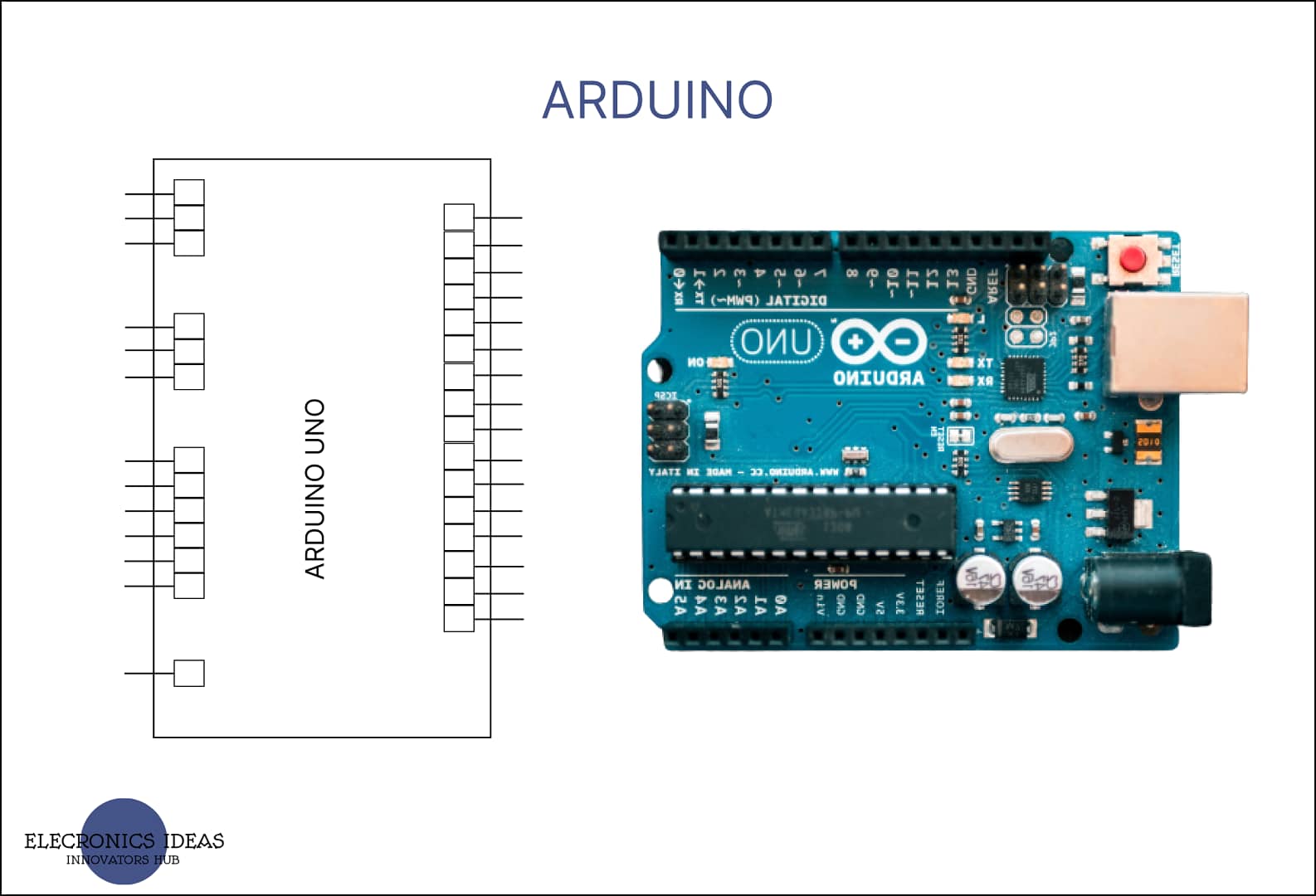
Schematic of an arduino

The above image contains the basic schematic of arduino UNO R3 powered by an ATmega microcontroller.
Parts of an Arduino

The basic parts/sections of an Arduino include;
Power section: The power section is marked red in the image above. This section contains input voltage which ranges from 6V to 12V. It also has 5V and 3.3V pins which can be used to power components connected to the arduino.
Analog input pins: The sections marked blue is for the analog input pins. Analog input pins receive input signals in analog form and the output is then converted to digital form. This pin is connected to a device that can supply input in analog form. Devices such as potentiometers and gas sensors can also produce analog signals. Instead of an input signal that is 1 or 0, you can get an input that can range from 1 to 1023. The analog-to-digital signal converter (ADC) converts the input analog signal to a digital output signal.
Digital pins: The section marked green is the digital pins. They can be used for both output and input. Here the input has only two states which are 1 and 0 (on and off respectively). Output is also connected to these pins. For basic operations, D2 through to D13 are used for both input and output.
Input types
Analog input: Analog signal is a time-varying signal that represents a time-varying quantity. This signal is different from a digital signal and is in continuous form. For example, a potentiometer can send an analog signal to an arduino by varying the voltage as you move the wiper. What happens is the varying voltage which serves as the quantity is represented by a signal (in arduino, the signal ranges from 1 to 1023).

// C++ code
//

int led = 0;
int signal = A0;
int result = 3;
void setup()
{
  pinMode(signal, INPUT);
  pinMode(result, OUTPUT);
}

void loop()
{
  for (led = 0; led <= 1023; led += led) {
    analogWrite(result, analogRead(signal));
  }
  delay(10);   // Delay a little bit to improve simulation performance
}
The example above illustrates how an analog signal is used to produce an output that is proportional to the input. The code is written in C++ and it is pretty much straightforward.
Digital input: In digital input, the input has just two(2) states they are on and off ( high and low or 1 and 0 respectively). The digital pins are used as both input and output, its from the code that the pin is identified if it serves as either an input or output source.
Either a pull-up or a pull-down resistor can be used to send a digital signal via a push of a button.
For a pull-up resistor, the input signal is connected between a resistor connected to Vcc and a switch connected to ground. The idea is that by default the input signal would be high as the input signal would be connected directly to Vcc through the pull=up resistor. Once the switch is closed, the current would flow through the path with lesser resistance which will now connect the input signal directly to ground. View the circuit below.

Below is the code for the above circuit.
// C++ code
// code for digital input signal using a pull-up resistor

int light = 3;
int signal = 12;

void setup(){
  pinMode(light,OUTPUT);
  pinMode(signal,INPUT);
}
void loop(){
 int signalState=digitalRead(signal);
  if(signalState==LOW){
    digitalWrite(light,LOW);

  }
  else{
    digitalWrite(light,HIGH);

  }
}
The same thing applies to pull-down circuits. The difference is that the position of both the switch and the pull-down resistor changes. In a pull-down circuit, the resistor is connected to ground while the switch is connected to Vcc. By default, the first signal is low until it is triggered to change via the click of a switch. Below is a circuit for pull-down resistor.

// C++ code
// code for digital input signal using a pull-down resistor

int light = 3;
int signal = 12;

void setup(){
  pinMode(light,OUTPUT);
  pinMode(signal,INPUT);
}
void loop(){
 int signalState=digitalRead(signal);
  if(signalState==HIGH){
    digitalWrite(light,HIGH);

 }
  else{
    digitalWrite(light,LOW);
     }

}
ICs such as operational amplifiers and 555 timer can also be used to send both digital and analog signals to the arduino.
Application and uses of arduino
The applications are unlimited but below are some of the application:
- Developing smart home devices with IOT capabilities.
- Development of smart car control systems.
- It can also be used in robotics and machine learning.
All the testing for both the code and the design of the circuits was done on TinkerCAD.
Related post


Very informative post
Thank you