Introduction to automatic security light system
An automatic security light system turns on when it senses darkness without anybody having to switch it on. In most houses, we use a manual security light system which has to be turned on manually. The major drawback of this system is that when no one is around to switch them on the compound remains dark and without light.
This automatic security light system operates on its own as long as it is supplied with voltage. The system makes use of LDR as a darkness sensor, and it follows the simple operation of an operational amplifier.
In this system, we would use an AC voltage source to power our system.
Electronic components used for this project
| S/NO | Components | Rating | Qty |
| 1 | LM358 (U1) | – | 1 |
| 2 | LM7812 (U2) | 12V | 1 |
| 3 | Transformer (T1) | – | 1 |
| 4 | Transistor (S1) | – | 1 |
| 5 | Diodes (D1,D2,D3,D4,D5) | – | 5 |
| 6 | LED (D6) | – | 1 |
| 7 | Capacitor (C1) | 10uF | 1 |
| 8 | LDR (RV1) | – | 1 |
| 9 | Potentiometer (RV2) | 10K | 1 |
| 10 | Resistor (R1, R3) | 1K | 2 |
| 11 | Resistor (R2) | 100 | 1 |
| 12 | Resistor (R4) | 5K | 1 |
| 13 | Capacitor (C2) | 1000uF | 1 |
| 14 | Resistor (R5, R6) | 10K | 2 |
| 15 | PCB board | – | 1 |
| 16 | Relay (S2) | – | 1 |
| 17 | Connecting wires | – | – |
| 18 | Head plug (SOR) | – | – |
| 19 | Light bulb (BULB) | – | 1 |
LM7812: LM7812 is a voltage regulator IC with three pins ( input, ground, and output). The function of this Ic is to regulate the input voltage and supply 12V at its output. The IC can regulate voltages from 14V to 35V and supply a constant output voltage of 12V.
Transformer: In this circuit, the transformer is used to decrease the input voltage.
Relay: A relay acts as a switch in this circuit. It uses an electromagnet to manually operate a switch.
Head plug: The head plug is used as a safe means to connect the circuit to an AC voltage source.
LM358: LM358 is an operational amplifier that has two operational amplifiers in a pack. In this circuit, the operational amplifiers are used as a comparator to compare voltages and give a corresponding output.
Potentiometer: A potentiometer is a variable resistor that has a fixed maximum resistance. It acts like two resistors in one pack and the resistance of those resistors is fixed based on the position of the knob. If the maximum rating of a potentiometer is 10K ohms, and the knob is placed such that one of the resistance is 4K ohms, the resistance of the other resistor is now 6K ohms. This gives room for easy adjustment of resistance without the need to be changing resistors physically.
Rectifying diodes: Rectifying diodes are a network of four diodes connected together for the purpose of converting AC voltage to DC voltage.
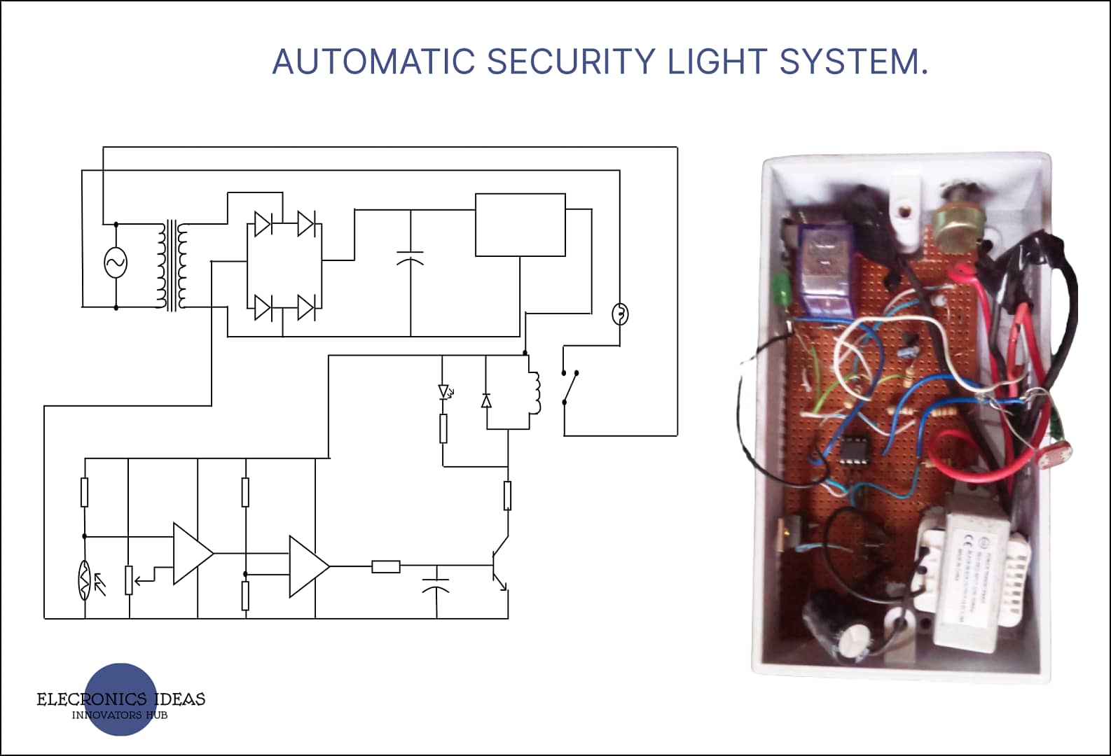
Block diagram of automatic security light

Circuit diagram of automatic security light system

Circuit analysis for automatic security light system
A 220VAC/13.5VDC, 50Hz, 125mA step-down transformer was used in the circuit to convert the 240V from the mains to 13.5V in the circuit. The 13.5V is then rectified to 12V.
Rectification is simply the process of removing the negative part of the alternating current (AC), hence producing the pulsating direct current (DC). In this work, this is achieved using the bridge rectifier which involves 4 diodes. Diodes only allow current to flow in one direction. In the first half cycle of AC, diode D1 and D2 are forward biased and D3 and D4 are reversed biased. In the second half cycle (negative half), diode D3 and D4 are forward biased and D1 and D2 are reversed biased. This combination converts the negative half-cycle into a positive. The diodes used in this circuit are 1N4007 PN junction diodes. The circuit also Contains a 1000uf capacitor which is primarily used to boost the 13.5V from the transformer to 14V which is the minimum input voltage required for the operation of the LM7812 regulator. In selecting the diodes used, the voltage drop across the diodes was considered. The 1N4007 Diode has an average forward current of 1A maximum a peak Inverse Voltage (PIV) of 1000V and a power dissipation of 3W. A single silicon rectifier diode in forward conduction mode develops a voltage of around 0.7 (but can be up to 2V).
Design and implementation of design
After all the testing and simulation, the system was put together on a PCB board. The system worked as expected and it was put to the test in real-life conditions. At different intervals, the following results were gotten.
| DAYS TESTED | TIME IT CAME ON | TIME IT WENT OFF |
| Monday | 6:59 pm | 6:35 am |
| Tuesday | 7:00 pm | 6:37 am |
| Wednesday | 7;01 pm | 6:35 am |
| Thursday | 7:03 pm | 6:35 am |
| Friday | 7:00 pm | 6:34 am |
| Average time ON = 7.00pm | Average time OFF = 6.35am |

Work explanation
When the system is powered from the mains (AC power source), the power unit which is made up of the transformer and the rectifier diodes and the voltage regulator ensures that just 12V (DC) reaches the main circuit.
The 12V is then used as a voltage source for the comparators which then proceed to compare the voltages at its inputs. For the comparator to output high, the voltage at the positive input of the first comparator needs to be higher than the voltage at the negative input of the comparator. For the voltage at the positive input to be higher. The system has to detect darkness over the LDR which will cause an increase in resistance.
The first comparator then feeds its output directly into the positive input of the second comparator. Once the first comparator outputs high, the second comparator automatically outputs high which then places a high voltage on the transistor thereby switching it on.
Switching the transistor on turns the LED (D6) on and at the same time causes the relay to switch on and turn on the bulb.
Application of automatic security light system
This system can be used in homes and industries to improve security. This system turns on and illuminates your household even if you are not around.
Conclusion/recommendation
The system performed as expected, further research can be carried out on this project to change the power source to a solar panel such that the system is independent of any operational limitation such as low voltage or no electricity.
Video demonstration of the project
Related posts


