Introduction to operational amplifiers
An operational amplifier also referred to as an op amp is a high gain DC voltage amplifier, meaning it can use a very small voltage difference between its input to control a much larger voltage at its output usually 100 thousands of times larger.
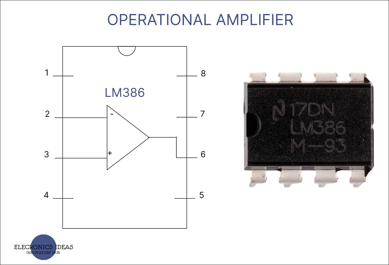
operational amplifiers come in different package types and they include Dip, surface mount, and metal can. A package may contain one, two, or four operational amplifiers. Basically, an operational amplifier is made of transistors, resistors, and a few capacitors and sometimes diodes are added.

The basic structure of an operational amplifier

The basic parts of an op amp are as follows.
Two input pins, inverting and non-inverting terminals. This leads takes the input signal of the amplifier or comparator.
Two DC supply leads, positive and negative. They usually determine the voltage limits of the output. It may be connected to the voltage source and ground how we connect our circuits or they may be connected to matching positive and negative power supply. One way to achieve this is by connecting a voltage divider made of resistors between a single power supply and the op amp.

The output terminal gives the output signal of the device.
Other special leads are used for fine-tuning the op amp.
How an operational amplifier works
The basic operation of an op amp is simple, the voltages at the input are compared (V- – V+= Vdiff) which determines whether the output saturates toward the positive supply voltage or the negative supply voltage.
Let’s say an op amp is connected to a 9V power supply and the input terminals non-inverting terminal (V1) and inverting terminal V2. If the voltage at the positive terminal is larger the output will go towards the positive supply voltage. If the voltage at the negative input is larger, the output goes towards the negative supply voltage, ground or 0V.
when the output reaches the supply voltage, it reaches saturation and it is at the maximum rated gain.
Note: Due to the voltage drop of the internal transistors that make the op amp saturation is slightly less than the maximum supply voltage.
Gain is the ratio or multiplier between the signal at the inputs and the signal at the output. Op amps are high-gain devices meaning the input voltage differential can be very small. A small voltage change can be used to control a much larger voltage change.
One of the most common op-amps is the LM741. From the datasheets, the typical gain is 200000. That is if you are running on a 9V battery only about 0.000045V differential is required at the input. If the differential voltage is not finely controlled, the output goes full throttle towards the positive or negative supply voltages.
That is the case for open loop circuits, any voltage at the input causes the output to saturate.
As a comparator, an op-amp can be used to make an AC-to-DC converter. Turning an AC sine wave into a DC square wave. With one input connecting to AC, as the sine wave flows the output continues switching back and forth between saturation positive and saturation negative converting AC to DC.
Controlling the gain, a feedback loop is created putting the op-amp in a closed-loop configuration. Feedback is achieved by connecting the output to one of the inputs. This is mostly done with the inverting terminal creating negative feedback. The voltage at the inverting input always equals the output voltage.
As the voltage at the positive terminal changes, the output voltage also changes. The loop self-corrects keeping the voltage at the inverting terminal nearly equal to that of the positive terminal just different enough to keep the differential microvolts needed to generate an output.
That is Vin=Vout
With the output looping straight back to the input, the op-amp acts as a buffer. Op-amps have high input impedance but low output impedance. Impedance is the measure of a circuit’s opposition to changes and electrical current
Using an op amp as a buffer can prevent the signal source from being affected by low currents. To control the gain, a feedback resistor is added to the loop. Changing the value of the feedback resistor changes how much of the output voltage gets feedback to the input, effectively controlling the amount of amplification between the input and output. If an active signal is connected to the inverting terminal the signal is amplified, But the polarity of this signal is reversed. And if the signal is connected to the non-inverting input. The signal is amplified and still maintains its polarity.
Uses of operational amplifiers op amp
Adder/summing circuits: can be used to put multiple input voltages into a single output voltage. Summing circuits can be used to make an audio mixer or to convert a digital signal like logic level binary or Bcd to an analog signal.
Subtractor/differential circuits: Have signals connected to both inputs. The voltage difference between the two inputs is then amplified. Differential amplifiers can be used to make a Wheatstone bridge or a sensor-activated circuit.
Integrator circuits: utilize a capacitor in the feedback loop instead of a resistor. The output of integrator circuits is proportional to both the amplitude and duration of the input signal. Integrators can be used to make analog-to-digital converters and wave-sharping converters.
Differentiator: A differentiator has a capacitor attached to the input instead of a resistor. The output is approximately proportional to the rate of change, the time derivative of the input.
Active low pass filter: is an example of a differentiator amplifier.
The op amp can be used in place of a 555 timer. An op-amp can be connected such that it behaves exactly like the various modes of a 555 timer.
Related posts


