Introduction of 555 Timer IC
555 timer Ic also referred to as NE555 is an eight (8) pin Ic that is used for switching circuits. They act as timers, oscillators, or flip-flops. The eight (8) pins on the 555 timer ic are as follows;
- Ground
- Trigger
- Output
- Reset
- Control voltage
- Threshold
- Discharge
- Vcc
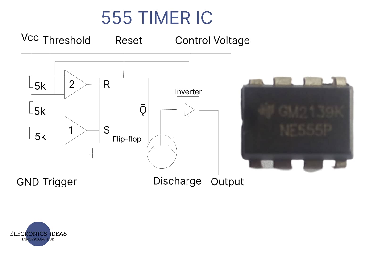
Block diagram of the 555 timer IC
The 555 timer ic is basically made of transistors and resistors but for better understanding, the IC is divided into 3 blocks. The blocks are;
- Voltage divider
- Comparator
- Flip-Flop

Voltage divider: This block is made of three (3) Kilo ohms resistors. The voltage divider is connected between the voltage source (Vcc) and the ground. The Vcc is usually between 5V – 15V. On the first comparator, the non-inverting terminal (positive terminal) takes 1/3Vcc while the inverting terminal (Negative terminal) of the second comparator takes 2/3Vcc. For example, If the Vcc is 9V. The inverting terminal of the second comparator takes 2/3Vcc which will be 6V and the non-inverting terminal of the first comparator takes 1/3Vcc which is 3V. The voltage gotten is used as by the comparators to compare with the voltages at both the trigger(pin 2) and threshold(pin 6).
Comparators: A comparator is a device that compares voltages at its input and outputs a digital signal based on the comparison. Basically, an Operational Amplifier(op-amp) is used as a comparator.

If the input at the non-inverting(positive) terminal is larger than the input at the inverting(negative) terminal the output is High. If the inverting terminal is higher the output of the comparator will be Low.
Looking at the 555 Timer the threshold (pin 6) is connected to the positive (non-inverting Terminal) and the negative is connected to the voltage divider. If the circuit uses a 9v battery. The inverting terminal will have 6v (that is 2/3Vcc). If the voltage at the threshold is higher than 6v the output will be High but if the voltage at the threshold is lower than 6v the output will be Low.
Again for the other comparator, the non-inverting(positive) terminal is connected to the voltage divider which is 1/3Vcc and the inverting terminal is connected to the trigger pin. Assuming we are using a 9v battery, the non-inverting terminal will take 3v ( that is 1/3Vcc). If the voltage at the Trigger pin is below 3v the Output of the comparator will be high voltage but if the voltage at the trigger pin is higher than 3v the output of the comparator will be low voltage.
Flip-Flop (SR-FF): SR-FF stands for Set Reset Flip Flop. The output of both comparators is connected to a Flip Flop. The output of the first comparator is connected to the Set pin(S) of the flip flop and the output of the second comparator is connected to the Reset pin(R) of the flip flop.

How a flip-flop works
The flip flop has two inputs set and reset(S and R respectively) and two outputs Q and ǭ. ǭ is always the inverse of Q. The set(S) input sets the output high while the reset(R) input sets the output low.
The truth table of SR-FF
| S/No | S | R | Q | ǭ |
| 1 | 0 | 0 | 1 | 0 |
| 2 | 0 | 1 | 0 | 1 |
| 3 | 1 | 0 | 1 | 0 |
| 4 | 1 | 1 | X | X |
A typical flip flop has two outputs, in a 555 timer only ǭ is used.
The Trigger pins(2) act like a starter pistol starting the timer and setting the flip flop but in other to get more than one tick off the timer the flip flop first needs to be reset. First, the voltage at the trigger pin must go above the voltage at the non-inverting terminal of the comparator setting the output of that comparator low then the voltage at the threshold pin needs to go above the voltage at the inverting terminal of the comparator setting the output high. This resets the flip-flop high. Both the S and R inputs of a flip-flop should never be high at the same time. If this happens the output begins to behave unpredictably. When both comparators output high the output is considered invalid.
Pins on the 555 timer IC
GROUND PIN (1): This pin is connected to the ground.
TRIGGER PIN (2): The trigger pin is used to set the output of the 555 timer high. The trigger pin is connected to the inverting terminal of the first comparator. The simplest way to set the output high is by connecting the trigger pin to the ground which is 0v.
OUTPUT PIN (3): The output pin is connected to the ǭ pin of the flip flop using an inverter. The signal at the output pin is the same as the signal on pin Q on the flip-flop.
RESET PIN (4): This pin is used to reset the flip flop. When reset is not in use it is connected to the Vcc. The reset pin is attached to the base of a transistor, the collector of the same transistor is connected to the flip flop then the emitter is connected to ground.
CONTROL VOLTAGE PIN (5): This pin is connected to the inverting input of the first comparator. Typically this pin has a voltage of 2/3 Vcc of the voltage but pin 5 can be used to adjust or control that voltage using a capacitor. This serves as a disturbance filter for the circuit.
THRESHOLD PIN (6): The threshold pin is used to reset the flip-flop and set the output to low. The threshold is connected to the non-inverting terminal of the second comparator.
DISCHARGE PIN (7): It is used together with external capacitors that are used to set the timing of the 555 timer, this applies for just astable and monostable modes. Pin 7 is connected to another transistor, with the base of the transistor connected to the output of the flip flop. The output of the flip-flop controls the base of the transistor. When the output is high ǭ is low which means the transistor is off and it allows the external transistor to charge up and eventually trigger the reset. After a while, the reset is triggered when the capacitor has charged up to 2/3 Vcc. The base voltage at the base of the transistor is set to high which makes the transistor act as a switch allowing the capacitor to discharge through the transistor to ground.
Vcc (8): This pin is connected to the power source.
Modes of operation of a 555 timer IC
555 timer Ic has 3 operational modes and they are;
- Monostable mode
- Bistable mode
- Astable mode
MONOSTABLE MODE: In mono-stable mode, the 555 timer can be triggered by one signal which will cause the 555 timer to output high and then automatically return to low after a certain period of time. Each activation causes the output of the 555 timer to go high. It is sometimes referred to as a one-shot timer.
BISTABLE MODE: In bistable mode, two different input signals are used to either set the timer output to high or low. Once triggered, the output signal stays in that state until the other input signal causes it to change.
ASTABLE MODE: In A-stable mode, the 555 timer is used as an oscillator. The 555 timer output never stays in one state. It switches or oscillates between the two states.
Applications of 555 timer IC
555 timer has many applications which include;
- 555 timer IC can be used for alarm systems such as anti-burglar alarm systems and water level alarm systems.
- It can be used for switching systems such as IR remote controllers.
- It can be used to send a digital signal to Arduino
- It can be used for scanners such as biometrics scanners.
Related posts


Wow
this is thrilling. I really learnt a lot, thanks Mr faveren Caleb.
I look foward to working with u
Thanks, Debby.