Introduction to ESP8266 (Nodemcu)
The ESP8266 is a compact Wi-Fi module that has gained popularity for its versatility in Internet of Things (IoT) applications. It integrates a powerful 32-bit microcontroller and a Wi-Fi transceiver into a small footprint, making it ideal for space-constrained projects. With its ability to run at 80 MHz or 160 MHz, it provides ample processing power for a range of tasks.
This module supports the 802.11 b/g/n wireless standard, ensuring compatibility with many Wi-Fi networks. It also boasts multiple GPIO pins for connecting peripherals, and a variety of built-in features like an ADC, SPI, I2C, and more. The ESP8266 can be programmed via the Arduino IDE, Lua scripting, or even the Espressif Native SDK, offering flexibility for developers of all skill levels.
Its low cost and ease of use have made the it is a go-to choice for hobbyists and professionals alike. Whether it’s for home automation, sensor networks, or any wireless-connected project, it provides a reliable and cost-effective solution. Its community support and extensive library resources further enhance its appeal, making it a cornerstone in the IoT development landscape.
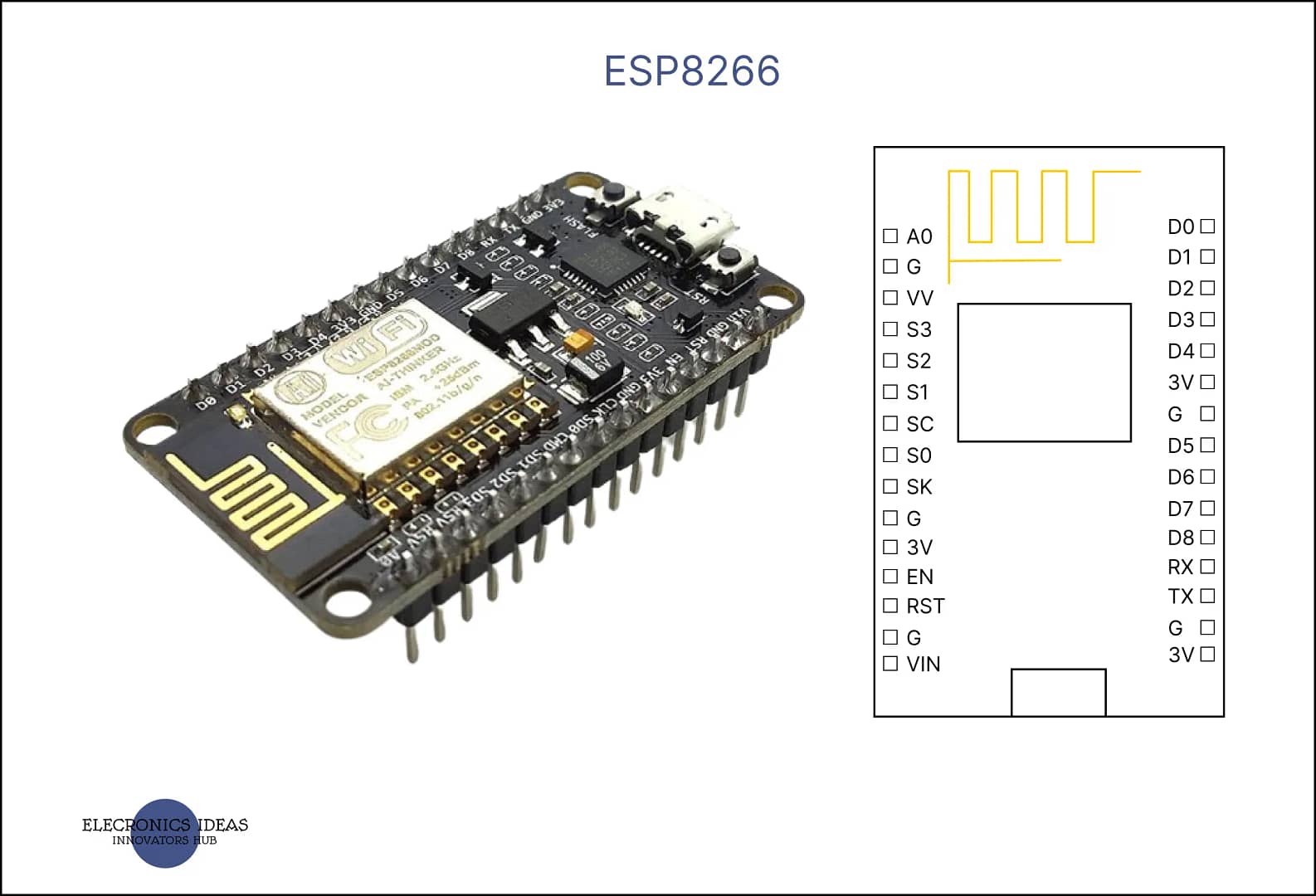
Schematics of ESP8266

- GPIO Pins: These are General Purpose Input/Output pins. It typically has 17 GPIO pins, but not all may be exposed on every development board. They can be used for digital read/write operations, and some support PWM (Pulse Width Modulation), I2C (Inter-Integrated Circuit), and interrupts.
- ADC0 (A0): This is the Analog to Digital Converter pin. It allows you to read analog voltages and is useful for interfacing with analog sensors.
- TX and RX: These are the Transmit and Receive pins, respectively, used for serial communication.
- CH_PD: Also known as Chip Enable or Chip Power-Down pin. It’s used to enable or disable the chip. It must be pulled high for the it to operate.
- RST: The Reset pin. When pulled low, it resets the microcontroller.
- VCC: This is the power supply pin. It typically requires a 3.3V supply.
- GND: The Ground pin.
- SPI Pins (SD1, CMD, SD0, CLK): These pins are used for Serial Peripheral Interface communication.
- I2C Pins: It doesn’t have dedicated I2C pins, it can use GPIOs to implement I2C communication through software.
- I2S Pins: For interfacing with audio devices, it provides an I2S (Inter-IC Sound) interface.
It’s important to note that some GPIO pins have specific behaviors during boot-up or have certain limitations. For example:
- GPIO0: Must be high on boot; otherwise, It enters flashing mode.
- GPIO2: Must also be high on boot for it to boot normally.
- GPIO15: Must be low on boot.
- GPIO16 (D0): Can be used to wake it up from deep sleep mode.
S2 (GPIO9) and S3 (GPIO10): These pins are usually connected to the internal flash memory of the ESP8266 and are used for SPI flash communication. It’s important not to use these pins for general I/O as it can interfere with the operation of the flash memory and cause it to malfunction.
S1: This pin is not commonly referenced in the documentation, and its function may vary depending on the specific module or development board you are using. It’s possible that S1 could be a designation used by a particular manufacturer for a specific purpose.

How to use ESP8266 in projects using Arduino IDE
Using the board with the Arduino IDE involves a few steps to set up the environment and start programming your module. Here’s a simplified guide:
Install the Arduino IDE: If you haven’t already, download and install the latest version of the Arduino IDE from the official Arduino website.
Add the ESP8266 Board to the Arduino IDE:
Open the Arduino IDE and go to File > Preferences.
In the “Additional Board Manager URLs” field, enter http://arduino.esp8266.com/stable/package_esp8266com_index.json and click “OK”.
Open the Boards Manager by going to Tools > Board > Boards Manager.
Search for “ESP8266” and click the “Install” button for the “ESP8266 by ESP8266 Community”.
Select Your ESP8266 Board:
After installation, go to Tools > Board and select your ESP8266 module from the list.
Choose the Correct Port:
Connect your ESP8266 to the computer and select the appropriate serial port under Tools > Port.
Write Your Code:
You can now write your code in the Arduino IDE or use one of the many examples available to get started. Here’s a simple testing code for the ESP-8266 board using the Arduino IDE. This code will scan for available Wi-Fi networks and print them to the Serial Monitor:
#include <ESP8266WiFi.h>

void setup() {
  Serial.begin(115200); // Start the serial communication
  // Set WiFi to station mode and disconnect from an AP if it was previously connected
  WiFi.mode(WIFI_STA);
  WiFi.disconnect();
  delay(100);
  Serial.println("Setup done");
}

void loop() {
  Serial.println("scan start");
  // WiFi.scanNetworks will return the number of networks found
  int n = WiFi.scanNetworks();
  Serial.println("scan done");
  if (n == 0) {
    Serial.println("no networks found");
  } else {
    Serial.print(n);
    Serial.println(" networks found");
    for (int i = 0; i < n; ++i) {
      // Print SSID and RSSI for each network found
      Serial.print(i + 1);
      Serial.print(": ");
      Serial.print(WiFi.SSID(i));
      Serial.print(" (");
      Serial.print(WiFi.RSSI(i));
      Serial.print(")");
      Serial.println((WiFi.encryptionType(i) == ENC_TYPE_NONE)?" ":"*");
      delay(10);
    }
  }
  // Wait a bit before scanning again
  delay(5000);
}
Upload the Code:
With the board connected and the correct port selected, click the “Upload” button to program the ESP-8266.
This code to your ESP-8266 module, open the Serial Monitor at a baud rate of 115200, and click the reset button on your ESP-8266 board. You should see the available Wi-Fi networks printed out in the Serial Monitor.
Applications of ESP8266
The ESP-8266 WiFi module is a versatile component widely used in the field of IoT (Internet of Things) due to its ability to connect microcontrollers to the internet. Here are some of its applications:
Home Automation: It’s commonly used in smart home devices, allowing users to control lights, thermostats, and other appliances remotely.
Industrial Control: In industrial settings, the ESP-8266 can monitor and control machinery, sensors, and processes.
Sensor Networks: It can be used to collect data from various sensors distributed across a wide area and send it to a central server for analysis.
Smart Plugs and Lights: The module can enable wireless control and scheduling of power outlets and lighting systems.
Baby Monitors: For personal safety applications, it can be integrated into devices that monitor and report on a baby’s environment.
Building Automation: It’s used to manage and automate building systems like HVAC, lighting, and security.
Intelligent Lighting: The ESP8266 can control lighting systems to adjust brightness and color based on user preferences or environmental conditions.


