The TDA2822 is a versatile and widely-used integrated circuit known for its role as a dual audio power amplifier. It’s designed to function in portable audio devices like cassette players, radios, and CD players due to its low voltage operation and power efficiency.
This IC stands out for its ability to operate on a supply voltage ranging from 3V to 15V, making it ideal for battery-powered applications. It’s capable of delivering up to 250 milliwatts of output power, which is quite substantial for its size.
The TDA2822 is appreciated for its low crossover distortion and low quiescent current, which contribute to its reliable performance and sound quality. It’s available in an 8-pin plastic dual in-line package, which is compact and suitable for small-scale electronic devices.
Whether you’re designing a simple audio amplifier for a DIY project or developing a portable music player, the TDA2822 can be an excellent choice due to its simplicity, efficiency, and effectiveness
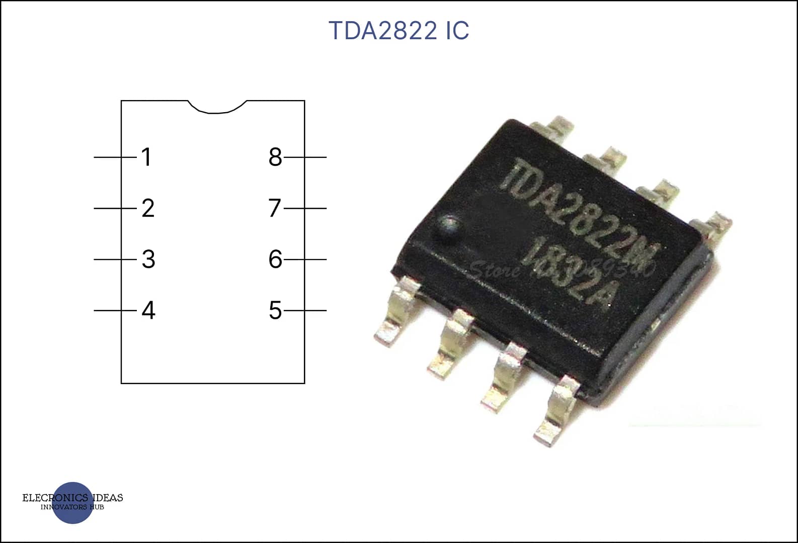
Schematics of TDA2822 IC

Pin 1 (Output 1): This is the output pin for the first amplifier. It provides the amplified audio signal for one channel.
Pin 2 (Vcc+): This pin is connected to the positive supply rail. It powers the IC and the supply voltage can range from 3V to 15V.
Pin 3 (Output 2): Similar to Pin 1, this is the output pin for the second amplifier, providing the amplified audio signal for the other channel.
Pin 4 (ground): This pin is connected to the negative supply rail or ground.
Pin 5 (Non-Inverting Input 2): The inverting input pin for the first amplifier. It is typically connected to ground through a capacitor.
Pin 6 (Inverting Input 2): The non-inverting input pin for the first amplifier. This is where the audio signal for the first channel is fed into the IC.
Pin 7 (Non-Inverting Input 1): The non-inverting input pin for the second amplifier. This is where the audio signal for the second channel is fed into the IC.
Pin 8 (Inverting Input 1): The inverting input pin for the second amplifier. Like Pin 6, it is typically connected to ground through a capacitor.
These pins allow the TDA2822 to be configured in different ways, such as in stereo mode for two separate channels or in bridge mode for a single, more powerful output. The IC’s design facilitates easy integration into various audio applications, providing flexibility and reliability for designers and hobbyists alike
Creating a simple stereo amplifier using TDA2822
Creating a simple stereo amplifier using the TDA2822 IC is a great project for audio enthusiasts and DIY hobbyists. Here’s a basic schematic for a stereo amplifier:
TDA2822 Stereo Amplifier Schematic:
Power Supply:
- Vcc+ (Pin 2): Connect to +3V to +15V DC
- Ground (Pin 4): Connect to Ground
Inputs:
- Non-Inverting Input 1 (Pin 6): Connect to the left audio source through a capacitor
- Non-Inverting Input 2 (Pin 7): Connect to the right audio source through a capacitor
- Inverting Inputs (Pins 5 and 8): Connect to Ground through capacitor
Outputs:
- Output 1 (Pin 1): Connect to the left speaker through a capacitor
- Output 2 (Pin 3): Connect to the right speaker through a capacitor
Volume Control:
- Connect a potentiometer to each input for volume control
Components Required:
- 1 x TDA2822 IC
- 2 x Speakers
- 4 x Capacitors for input signal coupling (10 µF)
- 2 x Capacitors for output signal coupling (1000 µF)
- 2 x Capacitors for power supply filtering (0.1 µF)
- 2 x Potentiometers (10K) for volume control
- 4 x Resistors (100Ω) for biasing
- Power source (battery or DC power supply)
This schematic is a starting point, and you can adjust the values of the capacitors and resistors based on the specific requirements of your project. The TDA2822 IC is capable of driving speakers with different impedances, so make sure to match the speakers with the IC’s output capabilities.

Applications of TDA2822 IC
These applications highlight the TDA2822’s flexibility and efficiency, making it a popular choice for designers and hobbyists alike in the realm of audio electronics. Here are some of the common applications and uses of the TDA2822 IC:
Portable Audio Devices: It’s often used in pocket cassette players, portable radios, and CD players because of its ability to operate at low voltages, making it ideal for battery-powered devices.
Headphone Amplifiers: The TDA2822 can be used to create small, efficient headphone amplifiers, providing a better listening experience without consuming much power.
Active Speakers: Its dual amplifier design makes it suitable for multimedia active speakers, offering a simple solution for stereo sound systems.
Hearing Aids: Due to its low noise output and ability to operate on low voltage, it can be effectively used in hearing aids.
Preamplifiers: The IC can serve as a preamplifier in audio systems, providing initial signal amplification before sending it to the main amplifier.
Wien Bridge Oscillators: The TDA2822 can be part of a Wien bridge oscillator circuit, which is used to generate sine waves.
Power Amplifiers: It can also be used in power amplifier applications where a small, efficient power boost is needed.
Audio Boosters: For devices that need a little extra volume, the TDA2822 can be used as an audio booster to increase the output without significant power draw.


