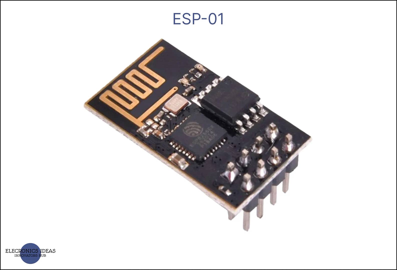
Introduction to ESP-01
ESP-01 is a Wi-Fi module that enables wireless communication and internet access for microcontroller projects. It is based on the ESP8266 chip, which has a 32-bit processor, a TCP/IP stack, and a Wi-Fi transceiver. It can operate in three modes: as an access point, as a station, or as both. It can be programmed using various firmware options, such as the Arduino IDE, NodeMCU, or MicroPython.
It has eight pins, two of which are used for power supply, two for serial communication, one for reset, one for chip enable, one for analog input, and one for general-purpose input/output. it is a small and low-cost module that can be integrated into various IoT applications, such as smart home devices, sensors, robots, or web servers.
ESP-01 is also known as a system on chip (SOC) because it can function as a standalone microcontroller, without the need for an external controller. It has limited memory and storage, which may restrict its capabilities and performance. Some users prefer to use it as a Wi-Fi shield for another microcontroller, such as Arduino, and communicate with it via serial commands. It is a versatile and popular module that offers a lot of possibilities for wireless and internet-enabled projects.
Schematics of ESP-01

The ESP-01 is a Wi-Fi module that has eight pins. Here is the datasheet
VCC: This pin provides a 3.3V power supply to the module. It should be connected to a stable 3.3V source with enough current capacity (at least 250 mA).
GND: This pin is the ground reference for the module. It should be connected to the ground of the power supply and the microcontroller.
TX: This pin is the serial transmit pin of the module. It can be used to send data to the microcontroller or another device. It can also be used as a normal GPIO pin (GPIO1) with some limitations (no PWM or I2C support).
RX: This pin is the serial receive pin of the module. It can be used to receive data from the microcontroller or another device. It can also be used as a normal GPIO pin (GPIO3) with some limitations (no PWM or I2C support).
RST: This pin is the reset pin of the module. It can be used to reset the module by pulling it low.
CH_PD (EN): This pin is the chip enable pin of the module. It can be used to enable or disable the module by pulling it high or low. It should be connected to 3.3V for normal operation.
GPIO0: This pin is a general-purpose input/output pin of the module. It can be used to control devices or read sensors. It can also be used to enter the programming mode of the module by pulling it low at boot. It has some special features, such as driving a relay or reading a push button.
GPIO2: This pin is another general-purpose input/output pin of the module. It can be used to control devices or read sensors. It can also be used to control the built-in blue LED of the module by pulling it low or high. It has some special features, such as driving a relay or reading a push button
How to use ESP-01 in projects
Esp-01 can be used to develop IOT-capable systems. In this example, we will focus on using the ESP with Arduino to turn on an LED. The IDE that will be used to program it is Arduino IDE.
- Connect the VCC pin of the ESP-01 to the 3.3V output of the arduino, and the GND pin to the ground of the arduino.
- Connect both the TX and the RX pin to the TX and RX pin of the arduino.
- Connect the Reset pin of the ESP-01 to a push button that is connected to the ground. This will allow you to reset the module manually.
- Connect the CH_PD pin of the ESP-01 to the 3.3V output of the power supply. This will enable the module to work normally.
- Connect the GPIO0 pin of the ESP-01 to ground. This will allow you to enter the programming mode of the module by pulling it low at boot.
- Go to file>>Preferences>>Additional Boards Manager URLs and paste these URLs: https://dl.espressif.com/dl/package_esp32_index.json,https://arduino.esp8266.com/stable/package_esp8266com_index.json then click on ok.
- Go to tools >> Boards>>Boards Manager and search for esp8266>>click install . click ok once you are done.
- Go to file>>examples>>ESP8266>>Blink
- Edit the LED_BUITIN to 0 through out the code. You can also choose to use the code below.
- Ensure that the right Board and port is selected in Tools. Then upload your code
- Unplug the USB from the system and pug it back in. This helps prevent error.
- When the code is uploading and it show the following either click the push button once or click the reset button on the arduino and hold until the upload is done.
- Disconnect both RX and TX from the arduino
- Remove the GPIO0 from ground an disconnect it to an LED through a resistor(1k ohms or 220ohms)
- Click the reset button to make the code run. This will make the LED start blinking

void setup() {
  pinMode(0, OUTPUT);     // Initialise the LED_BUILTIN pin as an output
}

// the loop function runs over and over again forever
void loop() {
  digitalWrite(0, LOW);   // Turn the LED on (Note that LOW is the voltage level
  // but actually the LED is on; this is because
  // it is active low on the ESP-01)
  delay(1000);                      // Wait for a second
  digitalWrite(0, HIGH);  // Turn the LED off by making the voltage HIGH
  delay(2000);                      // Wait for two seconds (to demonstrate the active low LED)
}
We are going to use Blynk application to control the LED (turn on and off).
- Connect both the RX and TX pins of the ESP to the arduino
- Connect the GPIO0 to ground.
- Create a blynk account or login to your account on the web dashboard
- Create a new template and select ESP 8266 as the board and wifi for connection type.
- Add the device and copy the auth token.
- Create a new datastream and set the pin to digital pin d0.
- Download and install the Blynk app on your smartphone and login
- Add a button widget and set it as a switch.
- Select the datastream that was created that’s d0.
- In the arduino IDE go to Sketch >>Include Library>> Manage Library >>Then search for blynk and install the Library.
- Go to file>>examples>>Blynk>>Board wifi>>ESP8266 Standalone
- Edit the code, paste the auth token from the blynk webpage.
- Change the SSID and password in the code to your WIFIs SSID and Password
- If your wifi does not have a password, allow the password quote empty =””
- Unplug the USB, and plug it back in then upload the code. Once the upload message appears click the push button once, or the reset button on the arduino till the upload is done.
- Disconnect both RX and TX pins of the esp-01 to the arduino RX and TX
- Connect the GPIO 0 to an LED through a resistor
- Open the app and turn on and off the LED.
Circuit Diagrams


Applications/ Uses of ESP-01
Some of the applications and uses of ESP-01 are:
- Home automation: it can be used to control devices such as lights, fans, sensors, etc. via WiFi. For example, you can use it to turn on/off a lamp using your smartphone or voice assistant.
- Internet of Things (IoT): it can be used to connect various sensors and devices to the internet and send/receive data. For example, you can use it to monitor the temperature and humidity of your room and display it on a web page.
- Robotics: It can be used to control robots or other moving objects via WiFi. For example, you can use it to drive a car or a drone using a joystick or a smartphone.
- Wireless communication: It can be used to communicate with other ESP-01 modules or other WiFi devices. For example, you can use it to create a chat system or a wireless network.
ESP 01 is a versatile wifi module that offers great potential for IoT applications. Its reliability, affordability, and ease of use make it a valuable tool for individuals and businesses alike. With its ability to connect devices seamlessly to the internet, ESP 01 opens up a world of possibilities for automation and remote control. Whether you are a hobbyist or a professional, ESP 01 is a recommended choice for integrating wifi capabilities into your projects.
Related post


