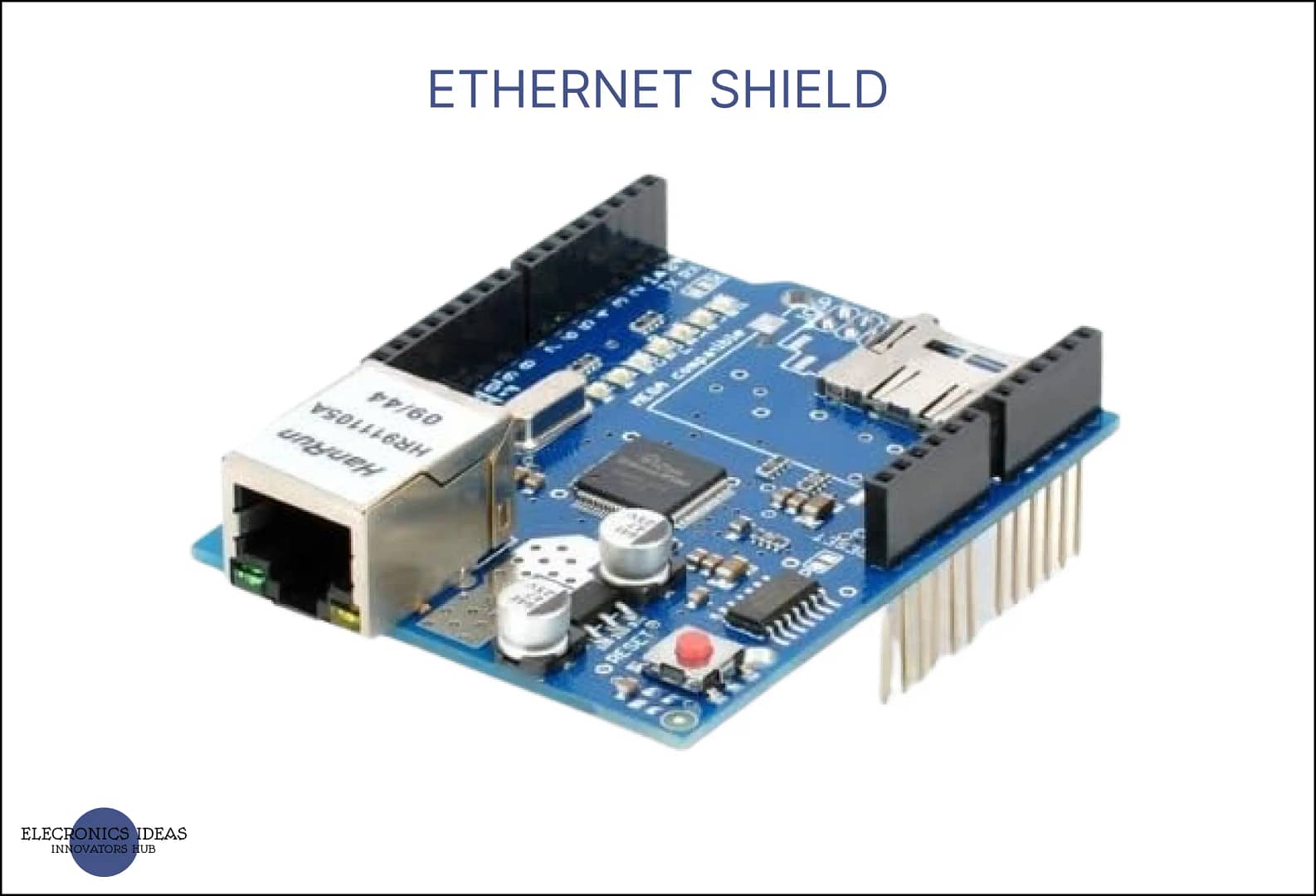
Introduction to Ethernet Shield(W5100)
Ethernet shield w5100 is a device that allows an Arduino board to connect to the internet and perform various network tasks. It is based on the Wiznet W5100 chip, which provides a TCP/IP stack and supports up to four simultaneous socket connections. The shield can be easily mounted on top of an Arduino board, using the long wire-wrap headers that extend through the shield.
The Ethernet shield (w5100) also has a micro-SD card slot, which can be used to store files for serving over the network, and a Power over Ethernet (PoE) module, which enables the shield to draw power from an Ethernet cable.
Ethernet shield (w5100) can be used for various applications, such as automation projects, remote controller applications, and social media displays. To use the shield, one needs to install the Ethernet library, which contains functions and examples for communicating with the internet using the shield. The library also supports the SD card and the PoE module.
It communicates with the Arduino board and the SD card using the SPI bus, which is on digital pins 10, 11, 12, and 13 on the Uno and pins 50, 51, and 52 on the Mega. The shield uses pin 10 to select the W5100 chip and pin 4 to select the SD card.
Schematic of Ethernet Shield

The Ethernet Shield has 28 pins. Here is a link to its datasheet. The pins are grouped into the following.
Communication pins: The shield communicates with the Arduino board using the SPI bus, which is on digital pins 10, 11, 12, and 13 on the Uno and pins 50, 51, and 52 on the Mega. These pins are used to transfer data between the W5100 chip and the Arduino board.
Power pins: The shield can be powered by either the Arduino board or an Ethernet cable, depending on the presence of a Power over Ethernet (PoE) module. If the PoE module is installed, the shield can draw power from the Ethernet cable using pins 1, 2, 3, and 6. Otherwise, the shield can be powered by the Arduino board using pins 5V and GND. The maximum voltage to power the ethernet shield is 9V.
Selection pins: The shield uses two pins to select different devices on the shield, such as the W5100 chip and the SD card. Pin 10 is used to select the W5100 chip and pin 4 is used to select the SD card. These pins cannot be used for general input/output.
How to use Ethernet Shield in circuits
We are going develop a circuit using ethernet shield together with arduino uno to control an LED using Blynk. We need the following components:
- Arduino Uno board
- -Ethernet shield W5100
- LED – 1k ohm resistor
- Breadboard
- Jumper wires
- USB cable
- Ethernet cable
- Blynk app on your smartphone You also need to install the Blynk library on your Arduino IDE and get an auth token from the Blynk app.
Below are the steps to follow to implement the circuit.
- Connect the Ethernet shield to the Arduino board and plug in the Ethernet cable
- Connect the LED and the resistor to the breadboard and the Arduino board (for example, connect the LED’s anode to pin 9 and the cathode to the resistor, then connect the other end of the resistor to the ground)
- Open the Blynk and create a new template under developer zone using a PC.
- Create a data stream and select digital pin. Then select d9 since we connected the LED to pin 9 and set it as output.
- Under devices, add a new device and select the template you created. Add a button widget and set the datastream as d9.
- Copy the auth token, Template name, Template ID from the app and paste it into the Blynk sketch
- Download the mobile app and add the button widget as well
- Open Arduino IDE and install the following Library
- Install Blynk library
- Install Ethernet library
- Select file>>example>>Blynk>>Getting Started>> Blink Blynk
- Paste the auth token, Template name, Template ID from the app into the Blynk sketch
- Upload the sketch to the Arduino board using the USB cable
- Open blynk either on mobile or desktop and turn off and on the LED.
- You can also copy and paste the code below into your sketch

#define BLYNK_TEMPLATE_ID           "TMPxxxxxx"
#define BLYNK_TEMPLATE_NAME         "Device"
#define BLYNK_AUTH_TOKEN            "YourAuthToken"


#include <SPI.h>
#include <Ethernet.h>
#include <BlynkSimpleEthernet.h>


void setup()
{

  Blynk.begin(BLYNK_AUTH_TOKEN);

}

void loop()
{
  Blynk.run();
}
Uses / Applications of Ethernet Shield (W5100)
The Ethernet shield W5100 is a device that allows you to connect your Arduino to the internet or a local network. With this shield, you can create various projects that involve internet connectivity, such as:
- Home automation: You can control and monitor different appliances and devices in your home remotely through a web browser.
- IoT (Internet of Things) projects: You can build various systems that collect and transmit data over the internet, such as weather monitoring, smart energy management, and more.
- Web server: You can host your own web pages and serve them to other devices on the network.
- Chat server: You can communicate with other users on the network using a simple chat application.
The Ethernet Shield (W5100) is an essential component for projects requiring internet connectivity. It enables seamless integration between an Arduino and the internet or a local network. This shield is particularly useful when developing projects that require online communication or remote control capabilities. By utilizing the Ethernet Shield, you can easily connect your Arduino to the internet and leverage its vast array of applications, such as monitoring sensors remotely, controlling devices through online platforms like Blynk, and accessing cloud services for data storage and analysis. Its versatility and reliability make the Ethernet Shield a valuable tool for any project involving internet connectivity.
Related post


1 thought on “A comprehensive guide on Ethernet Shield(W5100)”