Introduction to IOT based gas safety system
IOT gas safety system is a system that is meant to reduce then rate of gas incidents. A gas safety system is a device that can detect, prevent, or mitigate the hazards of gas leakage in various environments, such as homes, industries, or vehicles. Gas leakage can cause fire, explosion, poisoning, suffocation, or environmental damage.
An IOT based gas safety system typically consists of a gas detection mechanism, An iot based controller, a safety mechanism to reduce the concentration of gas in the room. This system basically works on reducing the concentration of gas a confined space. Gas damages are proportional to the amount of gas concentration.
Liquified Petroleum gas (LPG) is thrice denser than air which it settle in the lowest part of the house, its due to thee factor that an escape door is placed at the flour level to make LPG escape easier. In this project, an Arduino uno, an Ethernet shield and mq5 gas sensor is used. The ethernet shield gives it the IOT capability such that it can be controlled from any part of the world.
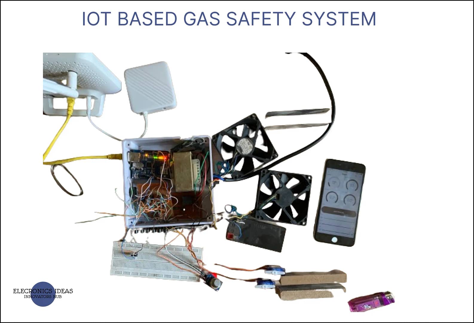
Hardware components used in this project
| S/NO | Component | Value | QTY |
| 1 | Ethernet shield | w5100 | 1 |
| 2 | Arduino uno | – | 1 |
| 3 | MQ5 | – | 1 |
| 4 | Servo motors | SG-90 | 2 |
| 5 | DC Fans | 12v | 2 |
| 6 | Lead acid battery | 12v | 1 |
| 7 | N-MOS | IRF530n | 2 |
Mosfet (N-MOS): An n mos mosfet is a type of metal-oxide-semiconductor field-effect transistor (MOSFET) that uses n-type (-) charge carriers (electrons) to conduct current. It has three terminals: source, drain, and gate. The source and drain are doped with n-type material, while the channel between them is doped with p-type material. The gate is insulated from the channel by a thin layer of oxide. When a positive voltage is applied to the gate, it creates an electric field that attracts electrons from the source to the channel, forming an n-type inversion layer. This allows current to flow from the source to the drain. The n-mos mosfet can be used as a switch or an amplifier in digital and analog circuits.
Ethernet Shield (w5100): An Ethernet shield is an add-on module that allows an Arduino board to connect to the internet via a wired network connection. It is based on the Wiznet W5500 Ethernet chip, which provides a network stack capable of both TCP and UDP. It supports up to eight simultaneous socket connections. The Ethernet shield has a standard RJ-45 connector, a micro-SD card slot, and a reset controller. It can be used with the Ethernet library to write sketches that communicate with the internet using the shield. The Ethernet shield is compatible with the Arduino Uno and Mega boards.
MQ5 gas sensor: An MQ5 gas sensor is a device that can detect and measure the concentration of combustible or harmful gases in the air, such as LPG, natural gas, coal gas, alcohol, and CO. It is composed of a heating element and a sensing element, both made of tin dioxide (SnO2). The heating element creates a high temperature that allows the gas molecules to react with the SnO2 surface. The sensing element measures the change in electrical resistance caused by the reaction. The MQ5 gas sensor has a high sensitivity and a fast response time. It can be used for gas leakage detection and prevention in various environments. The MQ5 gas sensor can be interfaced with an Arduino board using analog or digital pins, and its sensitivity can be adjusted by a potentiometer.
Servo Motors: A servo motor is a type of electric motor that can rotate or move to a specific position, speed, or torque based on an input signal from a controller. The controller uses a closed-loop feedback system to compare the desired setpoint with the actual output measured by a sensor and adjust the motor accordingly. A servo motor consists of three main components: a motor, a sensor, and a controller. Servo motors are widely used in industrial applications such as robotics, CNC machinery, and automated manufacturing, where high accuracy, fast response, and smooth motion are required.
Circuit diagram of IOT based gas safety system

How to connect IOT based Safety System
After implementing the above circuit, we can proceed to create a new template in Blynk. We are going to use Blynk for the IOT part of this IOT based gas safety system. You can read the previous post on how to use Blynk app. after understanding how the platform works, lets proceed to create a new template and add to or Arduino code. The system also uses the 12v charger with auto cut off.
- Login to the Blynk web portal
- Go to developer Zone, under My template and add a new template.
- Enter the name of the project as IOT based gas safety system or anything you choose, select Arduino as the hardware and ethernet as the connection type, enter a simple description for the project if you want.
- Under datastream, create 5 virtual pins. V9 for gas sensor, with unit as % and max integer as 100. V1 for the two servo motors with 90 as its max number. V2 for mode, to switch between automatic and manual mode. V4 and V5 for the fans the unit for the fans should be % with 100 as the max integer.
- Move over to the web dashboard, and add 4 guage widgets, 1 button and 3 slider widget.
- Set the first guage datastream to V9 for the gas level, set V1 as the datastream of another guage to indicate the level the door is open. Set V4 and V5 as the datastream for the remain two guages.
- Set V2 as the datastream for button.
- Set V4 and V5 as the datastream for two slider widgets.
- Set V1 as the datastream for the last slider widget.
- Open Arduino IDE and connect the Arduino using USB cable. NOTE: when you are connecting the Arduino to your computer, ensure to turn of the 9v power source that is powering the board
- Upload the following code to the Arduino
#define BLYNK_PRINT Serial

/* Fill in information from Blynk Device Info here */
#define BLYNK_TEMPLATE_ID "TMPL2-mYBvytu"
#define BLYNK_TEMPLATE_NAME "IOT automatic gas safety system"
#define BLYNK_AUTH_TOKEN "Ze6LHUA-TV-qLgwFm4hTS66DDAFFR4zF"

#include <SPI.h>
#include <Ethernet.h>
#include <BlynkSimpleEthernet.h>
#include<Servo.h>


int gasPin =A0;
int fan1 = 6;
int fan2 = 5;
int confan1;
int confan2;
int gasper;
int reading;
int fanSpeed1;
int fanSpeed2;
int mode;
int angle;


Servo servo1;
Servo servo2;

BLYNK_WRITE(V4)
{
 confan1=param.asInt();
  fanSpeed1 = map(confan1,0,100,0,250);
   analogWrite(fan1,fanSpeed1);
    Serial.println(confan1);
}
BLYNK_WRITE(V5)
{
 confan2=param.asInt();
  fanSpeed2 = map(confan2,0,100,0,250);
   analogWrite(fan2,fanSpeed2);
    Serial.println(confan2);
}

void gas(){
  reading =analogRead(gasPin);
  int another= analogRead(gasPin);
  gasper = map(reading ,0,1023,0,100);
   angle = map(another,0,1023,0,90);
   int mainSpeed=map(reading,0,1023,0,250);
  Blynk.virtualWrite(V9,gasper);
     if(gasper<39){
    servo1.write(0);
    servo2.write(0);
    Blynk.virtualWrite(V1,0);
    Blynk.virtualWrite(V4,0);
    Blynk.virtualWrite(V5,0);
     }
    if(gasper>40&&gasper<60){
    analogWrite(fan1,mainSpeed);
    analogWrite(fan2,mainSpeed);
    servo1.write(angle);
    servo2.write(angle);
    Blynk.virtualWrite(V1,angle);
    Blynk.virtualWrite(V4,mainSpeed);
    Blynk.virtualWrite(V5,mainSpeed);
    }
    if(gasper>60){
      Blynk.logEvent("gas","WARNING! GAS LEVEL TOO HIGH!");
    analogWrite(fan1,gasper);
    analogWrite(fan2,gasper);
    servo1.write(angle);
    servo2.write(angle);
    Blynk.virtualWrite(V1,angle);
    Blynk.virtualWrite(V4,mainSpeed);
    Blynk.virtualWrite(V5,mainSpeed);
}
}
BLYNK_WRITE(V2)
{
 mode=param.asInt();
}


BLYNK_WRITE(V1)
{
  servo1.write(param.asInt());
  servo2.write(param.asInt());
}


BLYNK_CONNECTED() {
  Blynk.syncVirtual(V1);
  Blynk.syncVirtual(V5 );
  Blynk.syncVirtual(V3);
  Blynk.syncVirtual(V4);
  Blynk.syncVirtual(V9);
}
void setup() {
  // put your setup code here, to run once:
Blynk.begin(BLYNK_AUTH_TOKEN);
pinMode(fan1,OUTPUT);
pinMode(fan2,OUTPUT);
Serial.begin(9600);
 pinMode(gasPin,INPUT);
 servo1.attach(A1);
 servo2.attach(A2);
}

void loop() {
  if(mode==1){
    gas();
  }
  else if(mode==0){
      reading =analogRead(gasPin);
  gasper = map(reading ,0,1023,0,100);
    Blynk.virtualWrite(V9,gasper);
  }
 Blynk.run();
}
How IOT based safety system works
The operation of the IOT based gas safety system is very simple. When gas leakage occurs, the system detects the gas and based on the amount of gas the it senses, it opens the doors according to the amount of gas and turns the fans on to help push the gas outside the room.
The IOT based gas safety system featured two modes, the automatic mode which operates when the system detects gas and deploy counter measures instantly without the help of a anyone. The manual mode of the IOT based gas safety system senses the gas but does not deploy safety measures immediately. The user has to manually tur on the fans and open the doors. The reason for this manual mode is that, at times we may induces gases such as insecticide and we want the gas to remain in the room for sometime so that it can kill the insect.
The IOT based gas safety system is a simple and yet very efficient way to reduce gas incidents.


Application of IOT based gas safety system
Some applications of IoT based gas safety system are:
- Home safety: An IoT based gas safety system can detect and prevent gas accidents in homes, especially in kitchens where LPG cylinders are used for cooking. The system can alert the user via a smartphone app, and also deploy counter measures automatically.
- Industrial safety: An IoT based gas safety system can detect and prevent gas accidents in industrial environments such as factories.
Related post


