Introduction to bi-directional counter with light control
A bi-directional counter with light control is a device that can measure the number of people entering and exiting a place at any point and turn on lights accordingly. It can be used for various applications, such as counting visitors in a museum, monitoring traffic flow, or controlling access to a restricted area.
One way to implement a bi-directional counter is to use an ultrasonic sensor, which is a device that emits and detects sound waves above the human hearing range. By measuring the time it takes for the sound waves to bounce back from an obstacle, the sensor can calculate the distance to the obstacle. If the distance changes over time, it means that something is moving in front of the sensor.
To count the objects or people moving in both directions, we need to use three ultrasonic sensors, one for each direction. We also need a microcontroller, such as Arduino, to process the signals from the sensors and display the count on an LCD screen. In this project, we made use of I2C module which reduces the number of pins to use for the LCD.
Hardware components used in this project
| S/NO | Component | Value | QTY |
| 1 | Arduino | – | 1 |
| 2 | Ultrasonic Sensor | – | 3 |
| 3 | Servo motors | – | 3 |
| 4 | I2C Module | – | 1 |
| 5 | Resistor | 1k | 1 |
| 6 | Transistor | NPN | 1 |
| 7 | Relay | – | 1 |
| 8 | Bulb | – | 1 |
I2C module: An I2C module is a device that allows communication between multiple components using the I2C protocol. The I2C protocol is a serial communication bus that uses two wires: SDA (data) and SCL (clock). It can act as a master or a slave, depending on whether it initiates or responds to the communication. It has a unique address that identifies it on the bus. It can be used to connect various devices, such as sensors, LCDs, EEPROMs to a microcontroller. It reduces the number of pins required for interfacing and simplifies the wiring.
Relay: An electromechanical relay is the most common type of relay. It consists of a coil of wire that creates a magnetic field when current flows through it, an iron core that enhances the magnetic field, a movable armature that is attracted or repelled by the magnetic field, and one or more sets of contacts that open or close the circuits. The contacts can be normally open (NO), normally closed (NC). The coil and the contacts are electrically isolated from each other.
Circuit Diagram of Bi-Directional counter with lights control

#include <Wire.h>
#include <LiquidCrystal_I2C.h>
#include <Servo.h>

LiquidCrystal_I2C lcd(0x27,16,2);

int users =0;
Servo serv1;
Servo ser2;
Servo servo3;

int ECHO1 = 3;
int TRIGGER1 = 2;
int ECHO2 = 10;
int TRIGGER2 = 9;
int ECHO3 = 6;
int TRIGGER3 = 7;

int light =8;

int DURATION1;
float DISTANCE1;
int DURATION2;
float DISTANCE2;
int DURATION3;
float DISTANCE3;

float count1;
float count2;
float count3;


void setup() {
  serv1.attach(A2);
  ser2.attach(A1);
  servo3.attach(A0);

  pinMode(TRIGGER1, OUTPUT);
  pinMode(ECHO1, INPUT);
  pinMode(TRIGGER2, OUTPUT);
  pinMode(ECHO2, INPUT);
  pinMode(TRIGGER3, OUTPUT);
  pinMode(ECHO3, INPUT);
  pinMode(light,OUTPUT);

  Serial.begin(9600);

  lcd.begin(16,2);
   lcd.init();
  lcd.backlight();

  start();
  delay(3000);
}


void loop() {
  digitalWrite(TRIGGER1, LOW);
  delayMicroseconds(2);
  digitalWrite(TRIGGER1, HIGH);
  delayMicroseconds(10);
  digitalWrite(TRIGGER1, LOW);
  DURATION1 = pulseIn(ECHO1,HIGH);
  DISTANCE1 = 0.0343*DURATION1;
  count1 = DISTANCE1/2;
  Serial.println(count1);


  digitalWrite(TRIGGER2, LOW);
  delayMicroseconds(2);
  digitalWrite(TRIGGER2, HIGH);
  delayMicroseconds(10);
  digitalWrite(TRIGGER2, LOW);
  DURATION2 = pulseIn(ECHO2,HIGH);
  DISTANCE2 = 0.0343*DURATION2;
  count2 = DISTANCE2/2;
  Serial.println(count2);

  digitalWrite(TRIGGER3, LOW);
  delayMicroseconds(2);
  digitalWrite(TRIGGER3, HIGH);
  delayMicroseconds(10);
  digitalWrite(TRIGGER3, LOW);
  DURATION3 = pulseIn(ECHO3,HIGH);
  DISTANCE3 = 0.0343*DURATION3;
  count3 = DISTANCE3/2;
  Serial.println(count3);


  if(count1<50){
   serv1.write(90);
   users++;
   digitalWrite(light,HIGH);
   lcd.clear();
     lcd.setCursor(0,0);
    lcd.print("Users:");
    lcd.setCursor(8,0);
   lcd.print(users);
   delay(2000);

  }
  else if(count1>=50){
    serv1.write(0);
    lcd.clear();
    lcd.setCursor(0,0);
    lcd.print("Users:");
    lcd.setCursor(8,0);
    lcd.print(users);
  }


  if(count2<50){
   ser2.write(90);
   lcd.clear();
     lcd.setCursor(0,0);
    lcd.print("Users:");
    lcd.setCursor(8,0);
    zero();
   lcd.print(users--);

   delay(2000);
  }
  else if(count2>=50){
    ser2.write(0);
    lcd.clear();
     lcd.setCursor(0,0);
    lcd.print("Users:");
    lcd.setCursor(8,0);
    lcd.print(users);
  }
  if(users==0){
    servo3.write(90);
    delay(2000);
    servo3.write(0);
    delay(2000);
    servo3.write(90);
    delay(2000);
    servo3.write(0);
    delay(2000);
    check();
  }
  else if(users>0){
  servo3.write(0);
  }

}

void check(){
    if(count3<60){
    lcd.clear();
    lcd.print("Users Present");
    digitalWrite(light,HIGH);
  }
  else if(count3>60){
    lcd.clear();
    lcd.print("Hall is Empty");
    digitalWrite(light,LOW);
  }
}


void zero(){
  if(users<0){
    users=0;
  }
}

void start(){
   lcd.setCursor(0,0);
    lcd.print("Bi-directional");
   lcd.setCursor(0,1);
    lcd.print("Counter");
}
How Bi directional counter with light control system works
We are going to explain the operation of this system in 5 stages.
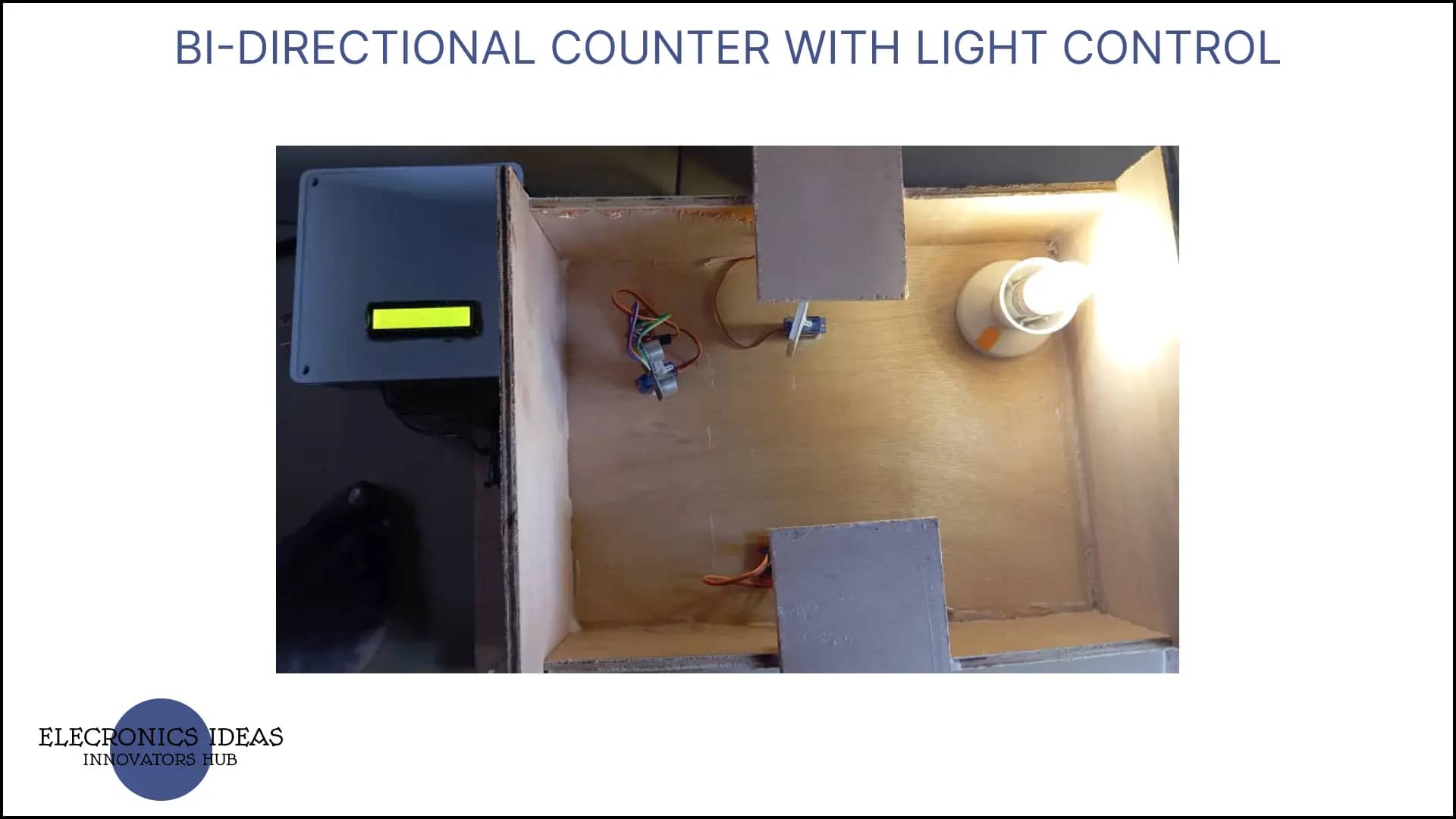
Sensing stage: Three ultrasonic sensors are set such that one counts from the entrance another at the exit and the last one is positioned in the building to check the interior when the total users reaches 0. When the entrance sensor picks up a signal it increases the number of users by 1. Once the exit sensor senses anybody it reduces the user by 1 and the last sensor checks the room to ensure its empty. The sensor sends a signal to the microcontroller.
Microcontroller: An Arduino processes the signals from the ultrasonic sensors. It determines the direction of movement based on which sensor that is triggered.
Counting Logic: The microcontroller runs a program that adds to the entry count when someone enters and subtracts from the exit count when someone leaves.
Display: The current number of people inside the room are typically displayed on an LCD screen connected to the microcontroller.
Light Control: The system controls the lights in the room using a relay that is triggered when someone enters the room and turns off when there is nobody in the room.


Applications of bi-directional counter with light control
They are a variety of applications across different sectors. Here are some of the key uses:
Facility Management: They help in monitoring the number of people present in a building, which is crucial for safety regulations and in case of emergencies.
Retail Analytics: In shopping malls and stores, these counters can track foot traffic, helping businesses understand peak hours and customer behavior.
Energy Management: They can be integrated with lighting and HVAC systems to optimize energy usage based on the occupancy of a room or building12.
Security: By keeping an accurate count of visitors, they can enhance security measures, ensuring that only a certain number of people are allowed access to a secured area.
Event Management: During events, they can assist in crowd control by providing real-time data on the number of attendees inside a venue.
Transport Hubs: Airports, train stations, and bus terminals use these systems to manage and analyze the flow of passengers.
Office Buildings: They can be used to monitor employee attendance and manage access to restricted areas.
Parking Lots: They can help manage parking space availability by keeping track of the number of vehicles entering and exiting.
Here is a link to Tinkercad
Here is a link to all the images on this project.
Hello Im trying to find things to improve my web siteI suppose its ok to use some of your ideas
Sure its okay