Introduction to liquid crystal display
Liquid Crystal Displays (LCDs) are used to enhance electronic projects by providing a visual interface for data presentation and interaction. They allow users to display information, messages, and sensor readings in a user-friendly format. When integrated into Arduino projects, Liquid crystal displays (LCD) help in the visualization of real-time data and make projects more engaging and informative.
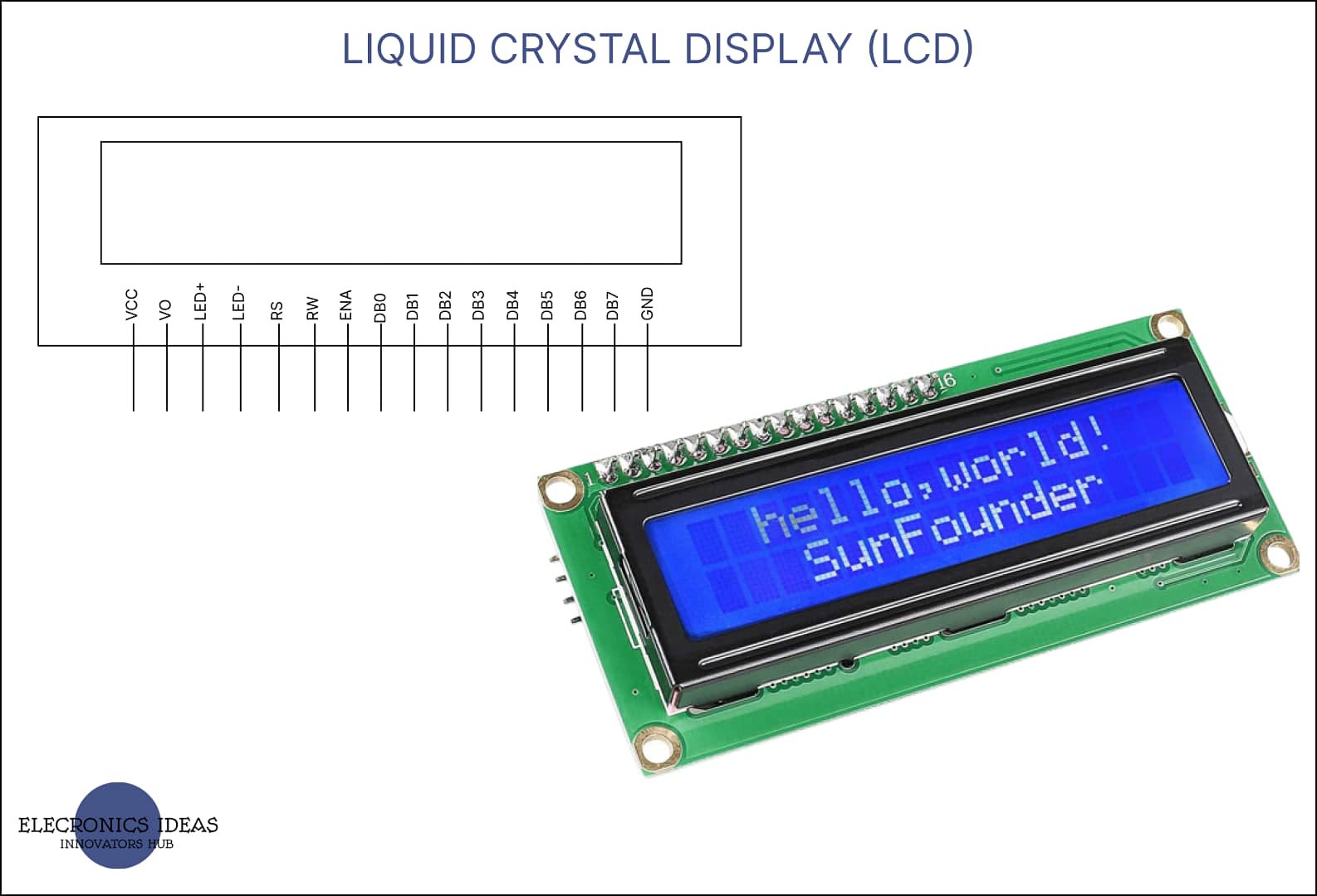
Arduino-compatible LCDs come in various sizes, ranging from standard 16×2 to 20×4 configurations. They use liquid crystals to control the passage of light, resulting in easily readable characters.
The integration process involves connecting the LCD module to the Arduino using a few digital pins for data communication and control.
Schematics of a liquid crystal display (LCD)

How to use liquid crystal display (LCD) in projects
Using a Liquid Crystal Display (LCD) in an Arduino project is a great way to display information and create better engagement in your project. This guide will provide a step-by-step approach to how to use liquid crystal display (LCD) in an Arduino project.
In this example, we will be using the following components:
- Arduino Board (in this example, we are using Arduino Uno R3)
- LCD Module (16×2 liquid crystal display (LCD) in this example but any LCD should do)
- Potentiometer (This is for adjusting contrast )
- Breadboard and jumper wires
Below is a step-by-step process on how to wire the components together.
- Connect the VSS (GND) (Ground) pin of the LCD to the GND pin on the Arduino.
- Connect the VDD (VCC) (Power) pin of the LCD to the 5V pin on the Arduino.
- Connect the V0 (Contrast) pin of the LCD to the middle terminal of the potentiometer.
- Connect one end of the potentiometer to the 5V pin and the other end to the GND pin on the Arduino.
- Connect the RS (Register Select) pin of the LCD to a digital pin on the Arduino (pin 12).
- Connect the RW (Read/Write) pin of the LCD to the GND pin on the Arduino.
- Connect the E (ENA) (Enable) pin of the LCD to a digital pin on the Arduino (pin 11).
- Connect the data pins D4, D5, D6, and D7 (DB4, DB5, DB6, and DB7) of the LCD to consecutive digital pins on the Arduino (Pin 5, Pin 4, Pin 3, and Pin 2, respectively).
- Connect the K (LED-) (Cathode) pin of the LCD to the GND pin on the Arduino.
- Connect the A (LED+) (Anode) pin of the LCD to the 5V pin on the Arduino through a 220-ohm resistor.

After the physical connection has been implemented, the next step is to proceed to the Arduino software (IDE) to write the associated code for this example. If you don’t already have it installed on your computer, go to the Arduino official website to get the IDE, then follow the guide on how to install it.
Below is the code for the above circuit.
#include <LiquidCrystal.h>

int seconds = 0;

LiquidCrystal lcd_1(12, 11, 5, 4, 3, 2);

void setup()
{
  lcd_1.begin(16, 2); // Set up the number of columns and rows on the LCD.

  // Print a message to the LCD.
  lcd_1.print("hello world!");
}

void loop()
{
  // set the cursor to column 0, line 1
  // (note: line 1 is the second row, since counting
  // begins with 0):
  lcd_1.setCursor(0, 1);
  // print the number of seconds since reset:
  lcd_1.print(seconds);
  delay(1000); // Wait for 1000 millisecond(s)
  seconds += 1;
}
The first thing to do is import the library for liquid crystal display (LCD). You import the library for LCD by writing the following code.
#include <LiquidCrystal.h>The next step is to initialize your Liquid crystal display (LCD) and identify all the pins that are connected to the Arduino. You can do that by writing the following code:
LiquidCrystal lcd_1(12, 11, 5, 4, 3, 2);After writing LiquidCrystal, you can choose to name it anything you want. For more context, check out the code below. Don’t use whitespace between the variables. Use an underscore.
LiquidCrystal choose_the_desired_name (12, 11, 5, 4, 3, 2);The next line sets up the columns and rows, of the liquid crystal display (LCD).
lcd_1.begin(16, 2); The next line is used more like a header for what you choose to display on the LCD.
lcd_1.print("hello world!");Moving the cursor is very important to display information in the right position. For a 16 X 2 display, we have two (2) rows. The first row is represented by zero (0), and the second row is one (1). This applies to all screen types.
lcd_1.setCursor(0, 1);Assuming you need to place particular information in column 10, row 1, you would do that by writing the following code: This ensures that the information remains in the right position and that there is no mix-up whatsoever.
lcd_1.setCursor(10, 1);How to use LCD with other components such as ultrasonic sensor
We would use the liquid crystal display (LCD) to display the distance between objects using ultrasonic sensors.


#include <LiquidCrystal.h>
int ECHO = 12;
int TRIGGER = 13;

int DURATION;
float DISTANCE;
float LED;
LiquidCrystal lcd(7, 6, 5, 4, 3, 2);

void setup() {
  // set up the LCD's number of columns and rows:

  pinMode(TRIGGER, OUTPUT);
  pinMode(ECHO, INPUT);
  Serial.begin(9600);
  lcd.begin(16, 2);
  lcd.print("FIRST DISPLAY");
  lcd.setCursor(0,1);
  lcd.print("DISTANCE :");

}

void loop() {
  digitalWrite(TRIGGER, LOW);
   delayMicroseconds(2);
  digitalWrite(TRIGGER, HIGH);
  delayMicroseconds(10);
  digitalWrite(TRIGGER, LOW);
  DURATION= pulseIn(ECHO,HIGH);
  DISTANCE = 0.0343*DURATION;
  float distance_cm = DISTANCE/2;
  Serial.println(distance_cm);

  lcd.setCursor(10,1);
  lcd.print(distance_cm);
  delay(1000);
  lcd.setCursor(13,1);
  lcd.print(" ");
}
Related post


1 thought on “A comprehensive guide on Liquid crystal display(LCD)”