Introduction to soil moisture sensors
Soil moisture sensors are innovative devices designed to measure the amount of moisture present in the soil. They play a crucial role in modern agriculture, environmental monitoring, and landscaping by providing valuable data to optimize irrigation practices, enhance crop yields, and conserve water resources.
These sensors employ various technologies to assess soil moisture content accurately and efficiently. By measuring the volumetric water content in the soil, these devices offer insights into whether the soil is too dry, adequately moist, or overly saturated. This information enables farmers, gardeners, and researchers to make informed decisions about when and how much to irrigate, helping to prevent both water wastage and the detrimental effects of under- or over-watering.
Soil moisture sensors come in different forms, including capacitance sensors, tensiometers, and time-domain reflectometry (TDR) sensors. Each type has its own unique method of measurement, allowing users to choose the sensor that best fits their specific needs and the characteristics of their soil.
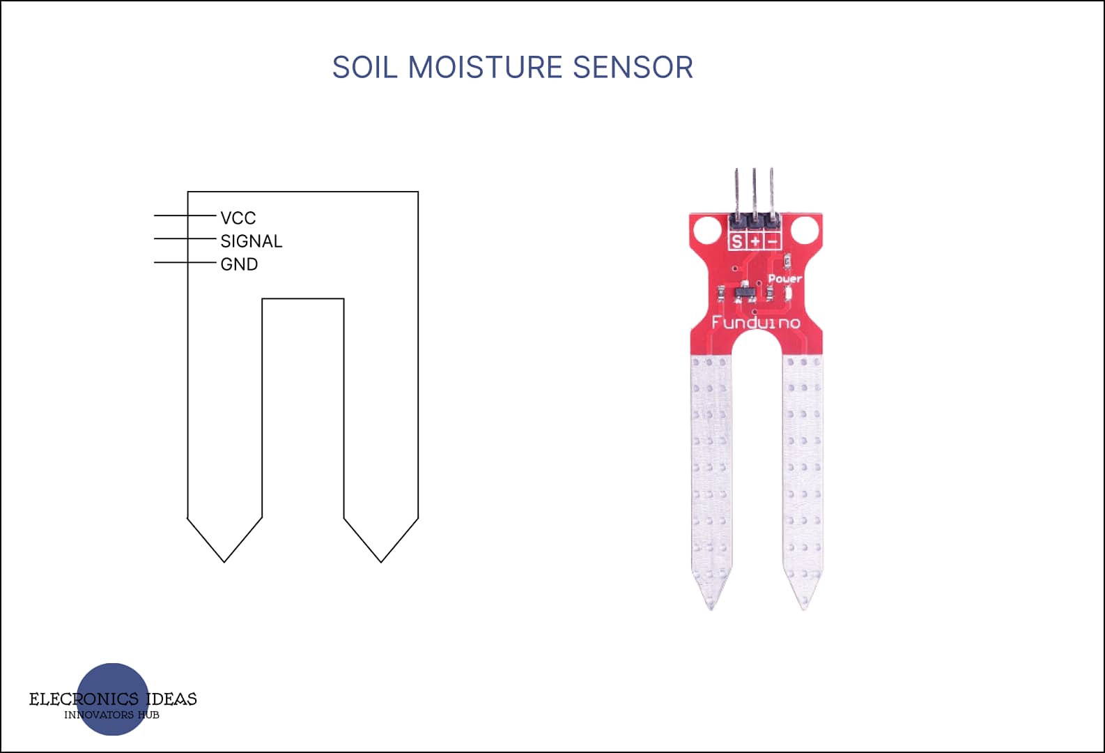
Schematics of soil moisture sensors

How to use soil moisture sensors in Arduino projects
Using a soil moisture sensor in Arduino projects is a great way to monitor and control soil moisture levels for various applications, such as automated irrigation systems, plant care projects, and environmental monitoring.
Here is an example that shows how to use a soil moisture sensor in a simple project. This example just makes use of a soil moisture sensor with an arduino and displays the amount of soil moisture content in the serial monitor of the Arduino software. You can get the arduino software here. In this example, we would make use of the following components.
- Arduino board (Arduino Uno R3)
- Soil moisture sensor
- Jumper wires
Below is the step-by-step method for connection of the sensor with arduino.
- First of all, connect the VCC pin of the soil moisture sensor to the 5V pin on the Arduino.
- Connect the GND pin of the sensor to the GND pin on the Arduino.
- Connect the A0 pin (analog input) of the sensor or to any analog input pin on the Arduino.


Upload the following code to your arduino using the arduino IDE.
int soilMoisturePin = A0; // Analog input pin for soil moisture sensor

void setup() {
pinMode(soilMoisturePin,INPUT);
  Serial.begin(9600); // Initialize serial communication
}

void loop() {
  int soilMoistureValue = analogRead(soilMoisturePin); // Read analog value from sensor
  int moisturePercentage = map(soilMoistureValue, 0, 1023, 0, 100); // Map value to percentage

  Serial.print("Soil Moisture: ");
  Serial.print(moisturePercentage);
  Serial.println("%");

  delay(1000); // Delay for stability
}
The first line of the code is used to identify the pin to which the signal pin of the sensor is connected. You can choose to name it anything but for this example we chose soilMoisturePin.
int soilMoisturePin = A0;In the void setup(), We have to fiirst of all identify the input source. Since we intend to display the soil moisture content in the serial monitor we would activate the serial monitor using the following code.
pinMode(soilMoisturePin,INPUT);
Serial.begin(9600);
In the void loop(), the first line informs the arduino on how to take the reading of the soil moisture content. Since we are dealing with a variable that changes often, we use analogRead such that the sensor only supplies the real-time quantity of moisture at any given time.
int soilMoistureValue = analogRead(soilMoisturePin);Using the map function of arduino, we would compare the analog signal range of the arduino to the percentage of moisture content in the soil. The analog signal range of an arduino is from 0- 1023. What happens is that the arduino makes 0% – 100% equivalent to 0 – 1023.
int moisturePercentage = map(soilMoistureValue, 0, 1023, 0, 100);The following code is for displaying the collected data on the serial monitor of the arduino IDE. The delay is to ensure that the arduino does not test the soil moisture until after one (1) second. This improves the stability of the system. You can choose to adjust how often you want the soil to be tested and the relevant data displayed.
Serial.print("Soil Moisture: ");
  Serial.print(moisturePercentage);
  Serial.println("%");

  delay(1000); // Delay for stability
How to use soil moisture sensors with LCD in arduino projects
In this example, the soil moisture content will be displayed on an LCD. Using LCD is a great way to display data. For this example, the following components are to be used.
- Arduino board (Arduino Uno R3)
- Soil moisture sensor
- LCD display (16×2)
- Potentiometer (for adjusting LCD contrast)
- Breadboard and jumper wires
- A power source (USB cable or external power supply)
- Resistor (for voltage divider circuit)
Let’s begin by connecting the LCD, below is the step-by-step process. You can also check out the main post on LCDs for a better understanding.
- Connect the VSS (GND) (Ground) pin of the LCD to the GND pin on the Arduino.
- Connect the VDD (VCC) (Power) pin of the LCD to the 5V pin on the Arduino.
- Connect the V0 (Contrast) pin of the LCD to the middle terminal of the potentiometer.
- Connect one end of the potentiometer to the 5V pin and the other end to the GND pin on the Arduino.
- Connect the RS (Register Select) pin of the LCD to a digital pin on the Arduino (pin 12).
- Connect the RW (Read/Write) pin of the LCD to the GND pin on the Arduino.
- Connect the E (ENA) (Enable) pin of the LCD to a digital pin on the Arduino (pin 11).
- Connect the data pins D4, D5, D6, and D7 (DB4, DB5, DB6, and DB7) of the LCD to consecutive digital pins on the Arduino (Pin 5, Pin 4, Pin 3, and Pin 2, respectively).
- Connect the K (LED-) (Cathode) pin of the LCD to the GND pin on the Arduino.
- Connect the A (LED+) (Anode) pin of the LCD to the 5V pin on the Arduino through a 220-ohm resistor.
For the soil moisture sensors connection,
- Connect the power to the 5V on the arduino.
- Connect the ground to the ground on the arduino
- Connect the signal pin to the A0 pin on the arduino.


#include <LiquidCrystal.h>

int soilMoisturePin = A0;

LiquidCrystal lcd_1(12, 11, 5, 4, 3, 2);

void setup()
{
  lcd_1.begin(16, 2); // Set up the number of columns and rows on the LCD.

  // Print a message to the LCD.
  lcd_1.print("SOIL MOISTURE");
  pinMode(soilMoisturePin,INPUT);

}

void loop()
{
  int soilMoistureValue = analogRead(soilMoisturePin); // Read analog value from sensor
  int moisturePercentage = map(soilMoistureValue, 0, 1023, 0, 100);
  lcd_1.setCursor(0,1);
  lcd_1.print(moisturePercentage);
  lcd_1.setCursor(4,1);
  lcd_1.print("%");
}
Related post


