Introduction to infrared(IR) receivers and remote
Most advanced systems depend on wireless communication via Infrared(IR) receivers and remote, and Arduino is one of the most common platforms for innovators to explore wireless systems. Infrared(IR) receivers and remotes serve as a gateway to seamless wireless control and interaction.
These components offer a user-friendly approach to designing and implementing wireless solutions that span from home automation to interactive gadgets.
The best part about infrared(IR) receivers and remotes is their accessibility and cost efficiency. Arduino’s intuitive programming interface and the straightforward integration of IR components create a great opportunity for enthusiasts and creators to design and develop wireless technology without extensive expertise.
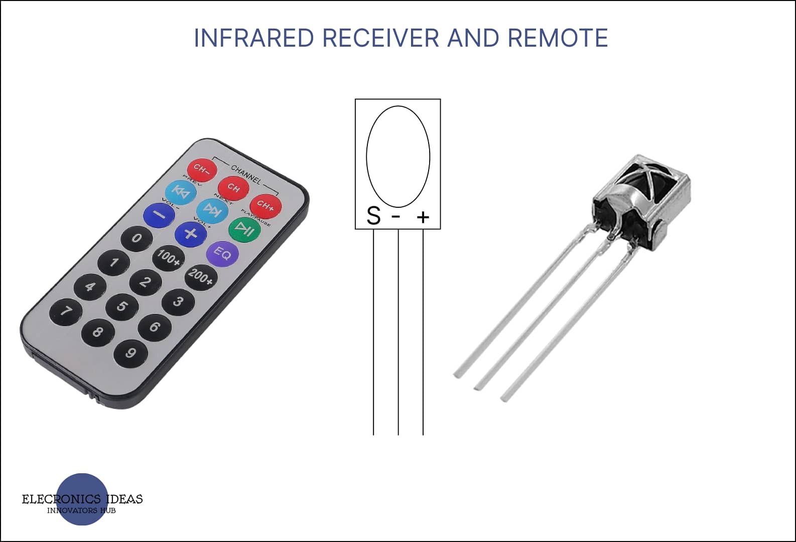
Schematics of infrared(IR) receivers and remote

How infrared(IR) receivers and remote work
In an Arduino project, infrared (IR) receivers and remotes work together to enable wireless communication and control. Here’s how they function:
An Infrared(IR) remote is a handheld device that emits infrared signals when you press its buttons. Each button on the remote is associated with a unique IR code that corresponds to a specific command or action. These IR codes are not visible to the naked eye, as they operate outside the range of visible light.
An infrared(IR) Receiver is a sensor that can detect and decode the IR signals sent by the remote. It is commonly used with Arduino projects to capture IR signals and translate them into usable data. The IR receiver module consists of a photodiode that detects IR light and a circuit that processes the detected signal. When an IR signal is received, the photodiode generates a voltage that corresponds to the modulated IR signal.
In an Arduino project, the IR receiver is connected to one of the Arduino’s digital input pins. The IR receiver detects the modulated IR signals from the remote and converts them into electrical signals that the Arduino can understand.
How to use infrared(IR) receivers and remotes in Arduino projects
Using an infrared(IR) receiver and remote in Arduino projects involves a few steps, from setting up the hardware to decoding the received IR signals. Here’s a basic guide on how to do it:
the hardware components needed are;
- Arduino board(Uno R3)
- Breadboard
- Infrared receiver and remote
- Jumper wires
The next step is to connect the receiver to the Arduino;
- Connect the “OUT” pin of the IR receiver to a digital input pin that supports PWM on the Arduino (pin 11).
- Connect the “GND” pin of the IR receiver to the Arduino’s ground (GND) pin.
- Connect the “VCC” pin of the IR receiver to the Arduino’s 5V pin.
The next step is to install the associated library, this step is applicable only if you have never used an IR receiver before.
You can do this through the Arduino IDE by navigating to “Sketch” > “Include Library” > “Manage Libraries” and then searching for “IRremote by Shirriff.” Install the library.


#include <IRremote.h>

IRrecv smart(11);

void setup(){
  smart.enableIRIn();
  Serial.begin(9600);
}
void loop(){

if(smart.decode()){
  Serial.println(smart.decodedIRData.decodedRawData,HEX);
  delay(500);
  smart.resume();
}
}
What this code does is display the decoded IR signal from the remote in the serial monitor as a hex code. From the top of the code, We first of all import the library. We do that by writing the following line of code.
#include <IRremote.h>The next step is to name the IR receiver and identify the pin it is connected to. In this example, we named our receiver smart and it is connected to pin 11. We name the receiver by using IRrecv name (pin)
IRrecv smart(11);In the void setup(), we will use the function name.enableIRIn(). The name before the enable is to be replaced by the name you chose to identify the receiver as. Since we intend to use the serial monitor, we will initialize it using Serial. begin(9600).
  smart.enableIRIn();
  Serial.begin(9600);
In the void loop(), an if statement is used to decode and print signals in the serial monitor. We use the function name.decode() in the parenthesis of the if statement. The name is to be replaced by the name of the receiver.
if(smart.decode()){

}
The next line prints the decoded signal in hex format in the serial monitor. We use the function name.decodedIRData.decodedRawData to get the decoded data from the IR receiver then we add, HEX to specify the format we want the decoded signal. In this case, we want the decoded signal to be in Hex code.
Serial.println(smart.decodedIRData.decodedRawData,HEX);A delay is added to ensure the receiver does not decode any signal immediately. This makes the work clearer and more readable. It prevents the receiver from decoding any signal until after the delay. The next line, name.resume() activates the receiver after the delay.
delay(500);
 smart.resume();
How to use Infrared(IR) receivers and remotes to control LED
In this example, we would use a remote to turn an LED on and off. To do that we would add an LED to the hardware components used in the previous example.
Hardware components needed include;
- Arduino Uno R3
- Breadboard
- Jumper cables
- Ir receiver and remote
- A resistor 1kohms and
- An LED
Connecting the components together.
- Connect the “OUT” pin of the IR receiver to a digital input pin that supports PWM on the Arduino (pin 11).
- Connect the “GND” pin of the IR receiver to the Arduino’s ground (GND) pin.
- Connect the “VCC” pin of the IR receiver to the Arduino’s 5V pin.
- Connect one end of the resistor to pin 9 and the other to the positive terminal (anode) of the LED. Then connect the negative terminal (cathode) to GND.


#include <IRremote.h>
IRrecv smart(11);
int light = 9;

void setup(){
  smart.enableIRIn();
  Serial.begin(9600);
  pinMode(light,OUTPUT);
}
void loop(){

if(smart.decode()){
  Serial.println(smart.decodedIRData.decodedRawData,HEX);
  delay(500);
  smart.resume();
}
    if(smart.decodedIRData.decodedRawData== 0xEF10BF00){
    digitalWrite(light,HIGH);
  }
   if(smart.decodedIRData.decodedRawData== 0xF30CBF00){
    digitalWrite(light,LOW);
  }
}
The above code is basically the continuation of the code from the first example. The difference is the two if statements that are added. The first if statement is to turn the LED on. To do this we click a button on the remote, in this example, number one (1) was pressed, and the hex code that appeared in the serial monitor was copied. In the parenthesis of the if statement, we compared the received code with the code for number one (1). The code is EF10BF00 we added 0x before the code so the Arduino knows we are dealing with hex code. So if the received signal is equal to that particular hex code then the LED turns on.
  if(smart.decodedIRData.decodedRawData== 0xEF10BF00){
    digitalWrite(light,HIGH);
  }
The same applies to the second code. the hex code used to turn off the LED is derived from the number zero (0). But this code turns the LED off.
 if(smart.decodedIRData.decodedRawData== 0xF30CBF00){
    digitalWrite(light,LOW);
  }
Related post


