Introduction to transistors
Transistors are active electronic components that can be used for amplification or switching circuits. We would look in detail at how transistors work. We would be focused on BJTs
The basic type of transistor is the bipolar junction transistor.
Bipolar junction transistors (BJT)
Bipolar junction transistor is similar to diodes. Diodes have a PN junction while BJTs have two (2) PN junctions. BJTs are essentially two diodes in a single package. The two main types of transistors are NPN transistors and PNP transistors.

NPN transistors have two N-type regions on either side and one P-type region in the middle while PNP transistors have two P-type regions and one N-type region.
Bipolar junction transistors have three leads, one going to each region. Typically the middle lead is the base labelled B. The remaining two regions go to the emitter labelled E and the collector labelled C.
Circuit symbols of transistors
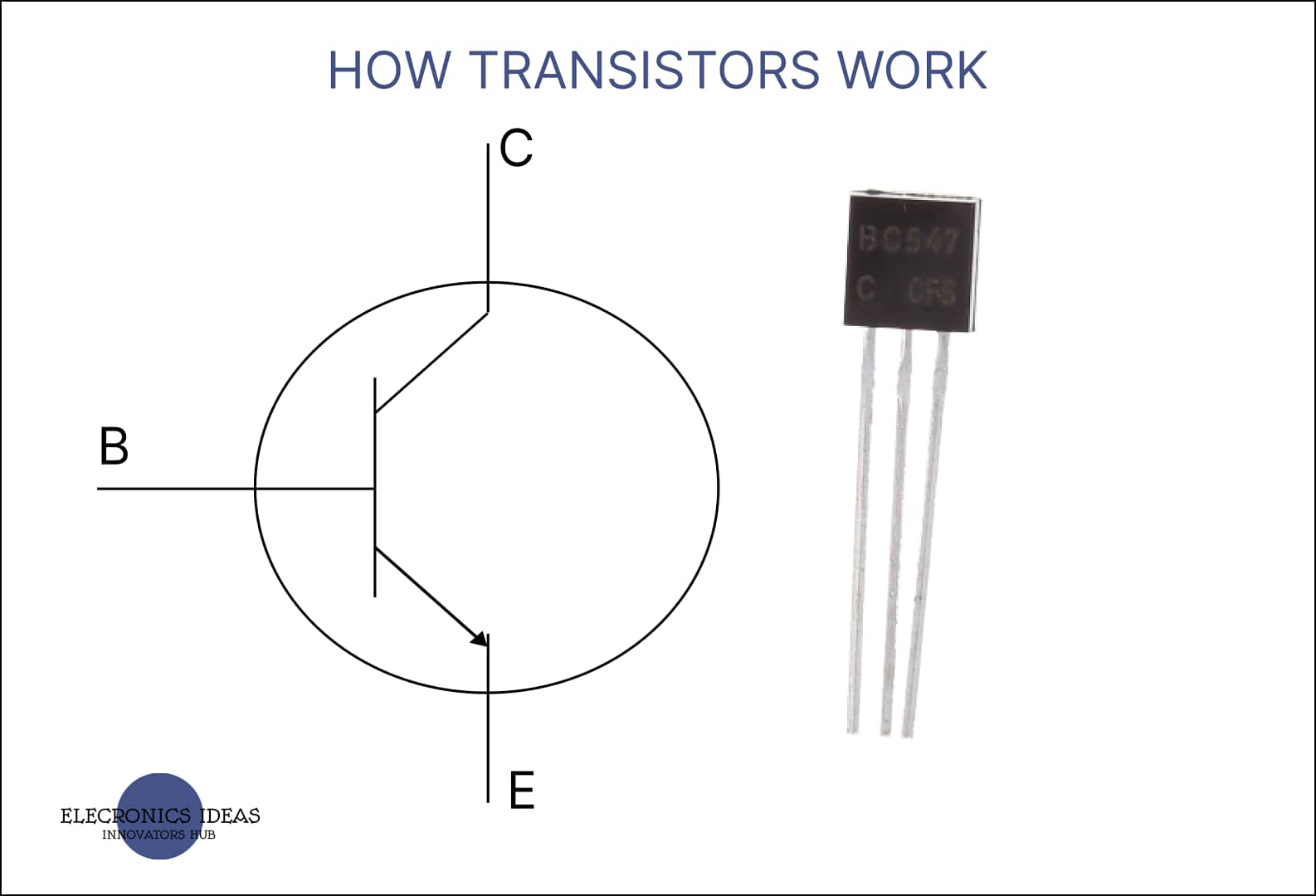
NPN transistor circuit symbol

For an NPN transistor, an arrow points out to one of its N-type layers which is the emitter. The base is always in the middle of the collector and the emitter. The emitter and the collector can appear on either side of the circuit symbol.
Note for NPN: to know the position of the emitter and collector, always check the arrow as the arrow is always pointing at the emitter.
PNP transistor circuit symbol

A PNP transistor is similar to an NPN transistor. Here the arrow points to the base from one of the p-type layers which is the emitter. The base is in the middle while the collector and the emitter are on either side of the p-type layer.
Note an arrow always points from the emitter to the base.
How transistors work
Instead of using a mechanical switch, a transistor can act as an electronic switch using a signal to turn it on and off.
The main signal of the circuit flows through the collector and emitter while the signal current flows from the base to the collector. The signal current at the base is what controls the switch. Current flowing from the base to the emitter can open the flow of current from the collector to the emitter.

How an NPN transistor works

For a standard NPN transistor, when a voltage of 0.7V is applied between the base and the emitter, the transistor turns on allowing current flow from the collector to the emitter.
An NPN transistor is normally biased such that the collector voltage is positive with respect to the emitter. The voltage across these two points is referred to as the collector-emitter voltage VCE. Then the base is connected to be positive with respect to the emitter. This voltage is referred to as the base-emitter voltage or VBE.
For example, if an LED is connected to a 9V battery with a resistor but it connects through a transistor this means that no current will flow in that part of the circuit until the transistor turns on. To turn the transistor on a VBE or base-emitter voltage of at least 0.7V is applied to the base of the transistor. Once the base of the transistor is applied with a voltage of 0.7V, this allows current to flow from the collector to the emitter of the transistor hence turning on the LED. Once the transistor turns on, the 9V becomes available.
How a PNP transistor works

For a PNP transistor, rather than needing a minimum of 0.7V on the base of the transistor, there needs to be a minimum difference of 0.7V between the VCE collector-emitter voltage and the VBE base-emitter voltage.
For example, if our circuit is using a 9V battery our base-emitter voltage needs to be no less than 8.3V for the transistor to turn on and allow the current to flow between the collector and emitter. But if the base-emitter voltage is 8.6V the circuit would not turn on as the difference is just 0.4V. Again, if the base-emitter voltage is 7V the circuit would turn on as the difference between the collector-emitter voltage and the base-emitter voltage is 2V.
For a difference of less than 0.7V, the transistor would be off, for a difference of more than 0.7V the transistor would turn on.
Note: In practical applications, low voltage applied to the base of a PNP transistor will turn on the transistor while high voltage will switch the transistor off.
Darlington transistors

A transistor can be used for amplification. One of the methods for current amplification is by combining two transistors into a Darlington pair. This can be done by combining two NPN or two PNP transistors together.
This is done by combining the emitter of the first transistor with the base of the second transistor. In a Darlington pair, the current is amplified by the first transistor then it is further amplified by the second. When a Darlington pair is contained in a single package it is referred to as a Darlington transistor. A Darlington transistor has three leads, one base, one collector and one emitter.
Darlington transistors are very useful as only a small amount of current is required at the base to get a gain of about a thousand or more. However, there is a significant voltage increase to be considered.
Abbreviations used in transistor calculations
- VBE – Base-emitter voltage
- VCE -collector-emitter voltage
- VCB – collector-base voltage
- IB – base current
- IC – collector current
- IE – emitter current
- VB – Base to GND
- VC – collector to GND
- VE – emitter to GND
Related posts


1 thought on “A simplified explanation of How transistors work”