Introduction of battery charge controller
Since the innovation of secondary cells, the Recharging of batteries has been made possible by passing direct current through them. However, challenges have risen on how to know when the battery is fully charged and to cut off charging automatically if the battery is fully charged since overcharging damages battery cells and shortens the lifespan of batteries.
This project describes the design and construction of a simple battery charge controller. It is developed to increase the lifespan of a battery during charging since it serves as a cut-off switch when the battery is fully charged to avoid overcharging. It also serves as a charge indicator for the battery at various battery voltage levels.
The building block of this design is on the various basic principle of electronic components such as operational amplifiers as a comparator of voltages, Transistors as an electronic switch, Zener diode for constant voltage supply, and resistors for current control at various points on the circuit, and LED for indications.
Electronic components used for this project
| S/NO | Components | Rating | Quantity |
| 1 | Op-amp LM324n (U1) | – | 1 |
| 2 | Transistor PNP (S1) | – | 1 |
| 3 | Resistor (R3,R5,R8,R11) | 5.1K | 4 |
| 4 | Resistor (R6,R9,R12) | 10K | 3 |
| 5 | Resistor R2 | 1.2K | 1 |
| 6 | Resistor R7 | 2.2K | 1 |
| 7 | Resistor R10 | 2.7K | 1 |
| 8 | Resistor R13 | 510 | 1 |
| 9 | Resistor R1 | 7.5K | 1 |
| 10 | Resistor R4 | 6.9K | 1 |
| 11 | Zener Diode 1N4007 (D1) | – | 1 |
| 12 | LED (D2,D3,D4) | – | 3 |
| 13 | LI-ON Cells | 3.7V | 2 |
| 14 | Connecting wires | – | – |
| 15 | PCB board | – | 1 |
| 16 | 12V power adapter | – | 1 |
Op-amp: An operational amplifier is used as a comparator in this circuit. LM324n is an IC with four op-amps.

Zener diode: A Zener is a heavily doped diode that allows current to flow backward when the zener voltage has been reached. Current only flows when the zener voltage has been reached.

Transistor: In this project, a PNP transistor is used. A PNP transistor as a switch turns on when a difference of 0.7V is reached between VCE and VBE. This means the transistor only allows current to flow through it only when the base has a minimum voltage difference of 0.7V.

Block diagram of the battery charge controller

Circuit analysis of battery charge controller
For op-amp to give positive voltage output when used as a comparator, the voltage at the non-inverting terminal V+ must be greater than the voltage at the inverting terminal V–
Mathematically expressed as Vo = (V+ – V–) * Vcc
We decided to make V– = 5.1V
Using the voltage divider rule given Vcc = 12V
R2 * Vcc / (R1 + R2) = Vref
Vref / Vcc = R2 / (R1 + R2)
5.1 / 12 = R2 / (R1 + R2)
Hence
R2 = 5.1k
R1 = 12 – R2 = 12 – 5.1 = 6.9k
For V1 = 5.2V or V1 > 5.2V
At Vb1 = 6.5V
V1 = R4 / (R3 +R4) * Vb1
R4 / (R3 +R4) = 5.2 / 6.5
Hence, R4 = 5.2k
R3 = 6.5 – 5.2 = 1.3k
At Vb2 = 7.5V and V2 = 5.2V
V2 = R6 * Vb2s / (R5 +R6)
5.2/7.5 = R6 / (R5 +R6)
R6= 5.2k
R5 = 7.5 – 5.2 = 2.3k
Vb3 = 8.3V
V3/Vb3 = R8 / (R7 + R8)
R8 / (R7 + R8) = 5.2 / 8.3
R8 = 5.2k
R7 = 8.3 – 5.2 = 3.1k
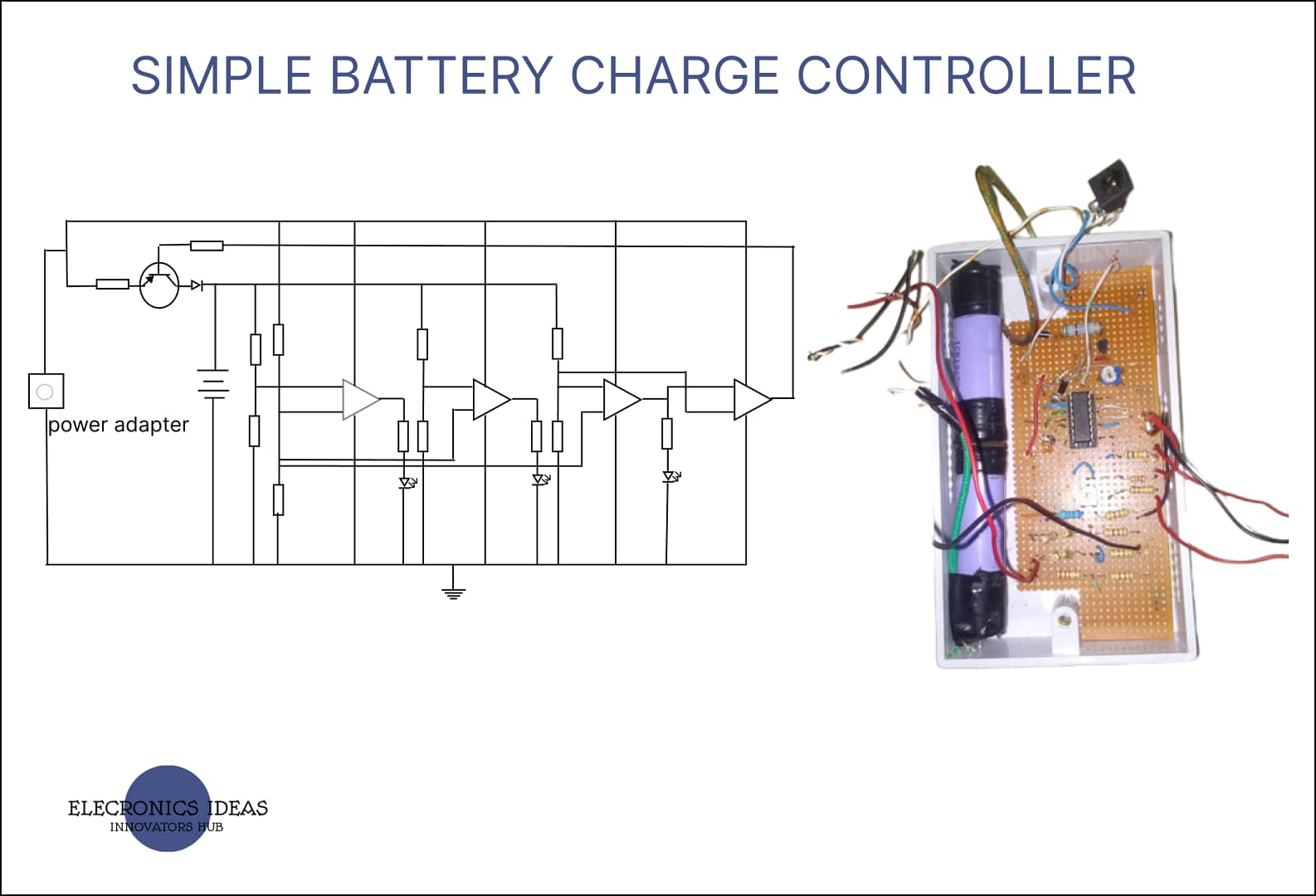
The circuit diagram of the battery charge controller

Design and implementation of battery charge controller
The circuit was developed on a breadboard and various tests were made.

Final work on battery charge controller
After all the successful tests, the circuit was built on a PCB board. The device was also covered in a protective case.

Work explanation of battery charge controller
The whole project is based on an operational amplifier as a comparator. From the moment the system is turned ON the operational amplifiers start comparing the voltages at its input and give output based on the output.
The system allows the battery to continue charging until it reaches 8.4V before it cuts off charging. From the first op-amp, once the voltage reaches a particular point and the voltage at the positive terminal is higher than the voltage at the negative terminal, the op-amp outputs high making the LED turn on indicating that the battery has charged above the first point.
The same process repeats itself until the third op-amp is fed straight to the positive terminal of the fourth op-amp. Once the voltage at the positive input of the fourth op-amp becomes higher than the negative input the output then goes to the PNP transistor where the voltage difference is going to be measured.
A voltage difference of less than 0.7V is needed for the transistor to turn off. The voltage difference is going to be taken by subtracting the collector-emitter voltage VCE from the base-emitter voltage VBE. If the voltage difference is more than 0.7V, the transistor would remain On.
The moment the voltage difference becomes less than 0.7V the transistor turns off cutting off the battery from the power source. This system would remain off until the battery is changed or it drains below 8.4V.
Note: PNP transistor is used in this simple battery charge controller because of its high collector current output.
Conclusion
The simple battery charge controller designed and constructed performed as expected. The intended aim of implementing a device that automatically cut-off charging when fully charged to prevent overcharging and senses changes in battery voltages at different levels and gives a corresponding visual indication through a light-emitting diode (LED) was achieved. The Components of the device are readily available in the market and hence can be easily purchased and implemented by students and academics.
Recommendation
This project work can be improved upon by employing a more efficient sensing mechanism. The Op-Amp and the BJT transistor can be replaced with zener diodes and MOSFET for batteries that charge at a higher current.
Related posts


I have some questions and observation, let’s start with this.
Firstly, the short description for the PNP transistor is kinda confusing, I would like if it description is reviewed, to the best of my knowledge, the PNP transistor turns on when the necessary bias has been done and when VBE is negative.
Secondly the diagram which the given mathematics calculations done should have appeared before the calculations itself, and every symbol used in the calculations should be indicated in the diagram.
The reason why the explanation for the PNP transistor is short is that there is a separate post that covers everything about transistors. Here is the link to it How transistors work
Thanks for your observations, going forward we would take that into consideration.
Alright, and again the time shown in the post is lagging.
Thanks for your response.
The correct time zone has been set thank you.