Introduction to diodes
We would focus on how diodes work and what role they play in circuit design. Diodes are electronic components that allow current to flow in one direction but not the other. Most common diodes have two leads. Some are clear with reddish-orange on the inside and a black stripe on one end while others are black with a silver stripe on one end. The stripe indicates which end is the cathode or the negative end.
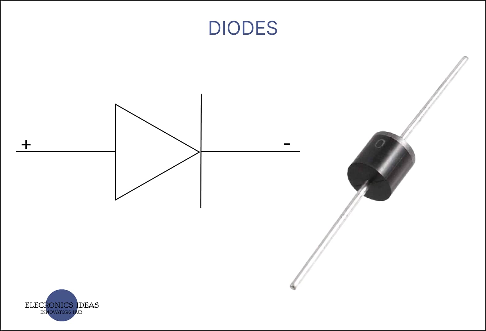
The circuit symbol of diodes

The line on the symbol matches up with the line on the diode itself. This helps you make sure the diode gets put into the circuit the right way. The cathode is where the line is and the anode is at the other end.
Understanding how diodes work (PN junction)
PN junction is also the basic block of a transistor. Diodes are made with semiconductor materials like silicon, germanium, and gallium arsenide. These semiconductors have four electrons on their outer shell which makes them unbalanced. For the semiconductors to be balanced eight electrons are needed to complete the outer shell. A process called doping is carried out to combine silicon and other semiconductor materials to balance off their outer shell.
For silicon diodes, two elements are added to them making two regions, the P-type region with positive charge carriers and the N-type region with negative charge carriers.

In the P-type region, the silicon is doped with an element like boron or aluminum these elements have only three instead of four electrons in their outer valence shells the missing electron creates a hole in the crystal structure instead of having the very stable eight electrons now some atoms only have seven but they still want that eighth electron to make them stable again. These holes are positive charge carriers.
In the N-type region, the silicon is doped with an element like antimony or phosphorous. These elements have five electrons in their outer shell, one more than what the silicon crystal structure needs. so, four of those electrons pair with the silicon atoms while the fifth becomes a free electron free to go wherever the current takes it. These free electrons are negative charge carriers
So, we have these two regions in the diode one doped with positive charge carriers and another doped with negative charge carriers. Where these two regions meet is referred to as the junction near the junction. The positive charges and the negative charges having opposing charges are drawn to each other like magnets. The free electrons in the N-type region move over and fill the holes in the P-type region because of the charged particles moving around the area near the junction. The P-type region becomes slightly negatively charged while the area near the junction in the N-type region becomes slightly positively charged. This area is known as the depletion zone.
Free electrons in the N-type region will continue moving into the holes in the p-type region causing the charges within the depletion zone to increase. These charges will eventually grow strong enough to begin repelling the charges in their region.
The N-type side gains enough positive charge in its depletion zone to repel the negative charges in the region and the same in the p-type side where the depletion zone gets enough negative charges to repel the positive charge in the region.

How to use diodes in circuits
Reverse bias
In a reverse bias mode, a diode is connected backward with its positive terminal (anode) connected to the negative terminal of the power source and the negative terminal of the diode (cathode) connected to the positive terminal of the power source.

Note: Diodes allow current to flow only in one direction.
The diode doesn’t allow current to flow until the voltage supplied passes the breakdown voltage of the diode which causes the diode to allow current to flow in the wrong direction. The electrons in both regions would be dragged backward in the opposite direction leading to an increase in the size of the depletion zone thereby stopping the flow of electrons.
Forward bias
In the forward bias mode, the negative terminal of the diode is connected to the negative terminal of the power source and the positive terminal of the diode is connected to the positive terminal of the power source.

What happens in the diode is that free electrons from the N-type region move from the cathode toward the depletion zone. When 0.7V is applied, the depletion zone shrinks till it disappears allowing the electrons to move freely into the P-type region to the anode of the diode.
The 0.7V required to overcome the depletion zone is also the forward voltage drop. That is if you are using a 9V battery, only 8.3 would be available at the other end of the diode.
Types of diodes
PN junction diodes: These are the common diodes. When connected in forward bias, they allow current flow but once they are connected in reverse bias they prevent current from flowing until a voltage higher than the breakdown voltage of the diode is applied.
Note: Exceeding the breakdown voltage may damage the diode.
Zener diodes: They are similar to common diodes but they are designed to allow current flow in both directions. In forward bias, it acts just like other diodes and conducts current. But in reverse bias, the Zener diode is heavily doped such that it allows only a certain voltage to pass through without damaging the diode. The voltage is known as zener voltage.
For example, a 3.3V zener diode would not allow current to flow until the supplied voltage reaches 3.3V. This means that, if the voltage supplied to the diode is less than the zener voltage, the diode would not allow current to flow. But if the voltage supplied is equal to or greater than the zener voltage, the diode would let the current flow. The voltage supplied to the zener diode is regulated to the zener voltage. That is, for a 3.3V zener diode, if Vin = 12V the output Vout would be regulated to 3.3V
They are other types of diodes such as
- Schottky diodes
- LEDs (light-emitting diodes)
- Laser diodes
- Photodiodes
Related posts


1 thought on “A simplified explanation of How diodes work”