Introduction to rain detector alarm system
A rain detector alarm system is a simple device that alerts households when it senses rainfall. In areas where rainfalls are common or during rainy seasons, it’s important that we get informed about rainfall on time so we make necessary arrangements before the rain starts falling heavily.
The device does not predict the weather it just detects the slightest raindrop on its sensor and makes an audible sound to notify people that it has started raining.
The system is based on 555 timer in A-stable mode, and it also uses the basic principle of a transistor as a switch.
Electronic components used for this project
| S/NO | Component | Rating | Quantity |
| 1 | Rain sensor (Sensor) | – | 1 |
| 2 | 555 timer (U1) | – | 1 |
| 3 | PNP transistor (S1) | – | 1 |
| 4 | Buzzer (BUZ) | – | 1 |
| 5 | LED (D1) | – | 1 |
| 6 | Connecting wires | – | – |
| 7 | PCB board | – | 2 |
| 8 | Capacitor (C1) | 10uF | 1 |
| 9 | Resistor (R1) | 100K | 1 |
| 10 | Resistor (R2) | 470K | 1 |
| 11 | Resistor (R3) | 3.9K | 1 |
| 12 | Resistor (R4) | 1.2K | 1 |
| 13 | Resistor (R5) | 5.1K | 1 |
| 14 | Resistor (R6, R7) | 7K | 2 |
| 15 | Resistor (R8) | 500 | 1 |
| 16 | Battery (Vcc) | 9V | 1 |
555 timer is used as an oscillator in A-stable mode. In a-stable mode, the output of the 555 timer oscillates between on and off states continuously.
The PNP transistor is used as a switch to connect the reset button to the power source (Vcc).
The rain sensor used is a locally made accessory. A PCB board was used to fabricate the panel sensor. The holes on the board were looped such that the holes on the PCB board serve as the opening in the circuit and once water touches the surface of the board it closes the circuit.

Buzzer and the LED both serve as indicators for when the system is triggered.
Block diagram for rain detector alarm

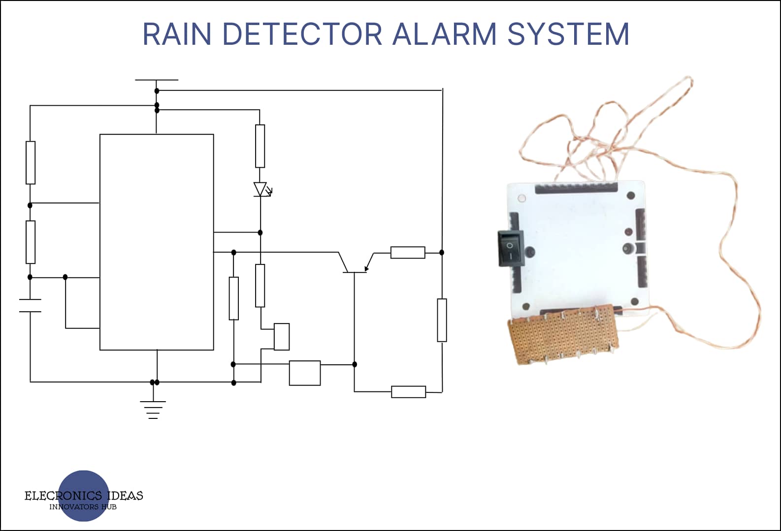
Circuit diagram of rain detector alarm system

Circuit analysis for the rain detector alarm system
The time T(ON) for the timer = 0.693*(R6+R5) *C
T(ON) = 0.693 X (5.1k+7k) X 10uF = 83.85 milliseconds
Therefore T(ON) = 83.85 milliseconds
The T(OFF) = 0.693*R2 *C
T(OFF) = 0.693 X 7k X 10uF = 35.34 milliseconds
Therefore T(OFF) = 35.34 milliseconds
Period of oscillation T = T(ON)+T(OFF)
T = 0.693 X (R6+R5) X C + 0.693 X R2 X C
T = 0.693 X (R6+2R5) X C
T = 0.693(7k+10.2k) X 10uF = 119 milliseconds
Therefore period T =119 milliseconds
Duty circle %D = (T(ON)/T) X 100
%D = (35.34/119) X 100 = 70.35%
Therefore Duty circle = 70.35%
Frequency f = 1/T
f = 1/0.693 X (R6+2R5) X C
f = 1.44/(7k + 10.2k) X 10uF = 8.390Hz
Therefore Frequency f = 8.390Hz
Design/implementation of rain detector alarm
The above schematic design was implemented on a breadboard and all the necessary tests were carried out to ensure the system worked as expected. everything worked as expected and the sensor worked as it should.

Final work
After all the tests were carried out on a breadboard and the system worked well. The system was then implemented on a PCB board for a more compact and professional look.

Work explanation of the rain detector alarm system
For this particular system, the explanation would be broken down using the block diagram.
Input/Sensory Unit
This unit is made of a water-sensing panel. A rain sensor panel is a simple tool used to detect rain. It works like a simple switch. When there are rainwater drops on the surface of the panel, the switch closes. This completes the circuit, which then triggers the buzzer. Without the water on the surface of the panel, the circuit is open. From the design of the rainwater sensor panel, you would notice holes in the panel. These holes make the circuit an open circuit. By default, there will be no conduction between the wires and so the resistance between the contacts is very high. On the other hand, when it does rain, a conductive path forms between the tracks and so the resistance between the contacts decreases. When this happens, the wires in the circuit start conducting, and then through the transitory circuitry, the NE555 timer is triggered.
Switching Unit
This unit consists of the BC327 Transistor (PNP). When rain drops on the rain sensor panel and shorts the circuit, the base of the transistor receives a voltage from the sensing unit almost quickly.
Because of the voltage at the base, the transistor becomes ON (initially it was in an OFF state), and current starts flowing from the collector to the emitter. The BC327 transistor basically acts as a switch in this circuit.
The Oscillating Unit
This unit consists of the NE555 Timer IC. The reset pin 4 of the IC receives a voltage from the transistor and turns ON. In this project, the IC is in A-stable mode. In this mode, the output oscillates between high and low. So, the output once triggered would continue moving between high and low until the system is turned off manually or the sensor panel becomes dry. The capacitor and resistors in conjunction with the discharge pin (7) control the time delay for each state.
The Output Unit
The output unit consists of a buzzer and an LED. When the 555 Timer IC gets a voltage from the transistor, it switches ON. Because the output of the IC oscillates between high and low, this causes the buzzer to start beeping and the LED produces a blinking light accordingly. The buzzer generates an oscillating sound.
Conclusion of rain detector alarm
At the end of the project, a rain detector alarm system was successfully designed and implemented. The rain/water detector alarm system will be useful in both domestic and industrial applications. The device when properly placed to receive the first set of droplets of rainwater can save the user from damaging possessions that were being sun-dried and prevent rain from entering homes, offices, and silos.
Recommendations rain detector alarm
This project work can be improved upon by employing a more efficient sensing and alarm mechanism. Some examples include getting a message on the phone when it rains outside.
Related posts


Beautiful.
Thanks Kelvin and as per your request we changed the arrangement of the post.
Cheers.