Introduction to the operational modes of a 555 timer
A 555 timer is one of the most used integrated circuits for most electronic projects. We would discuss in detail all the operational modes of a 555 timer. It functions in different circuits as either a switch, a flip-flop, or an oscillator. A 555 timer can be used in place of a microcontroller and the without the use of writing a program. It is very important to understand all the operational modes of a 555 timer so as to be able to use it effectively.

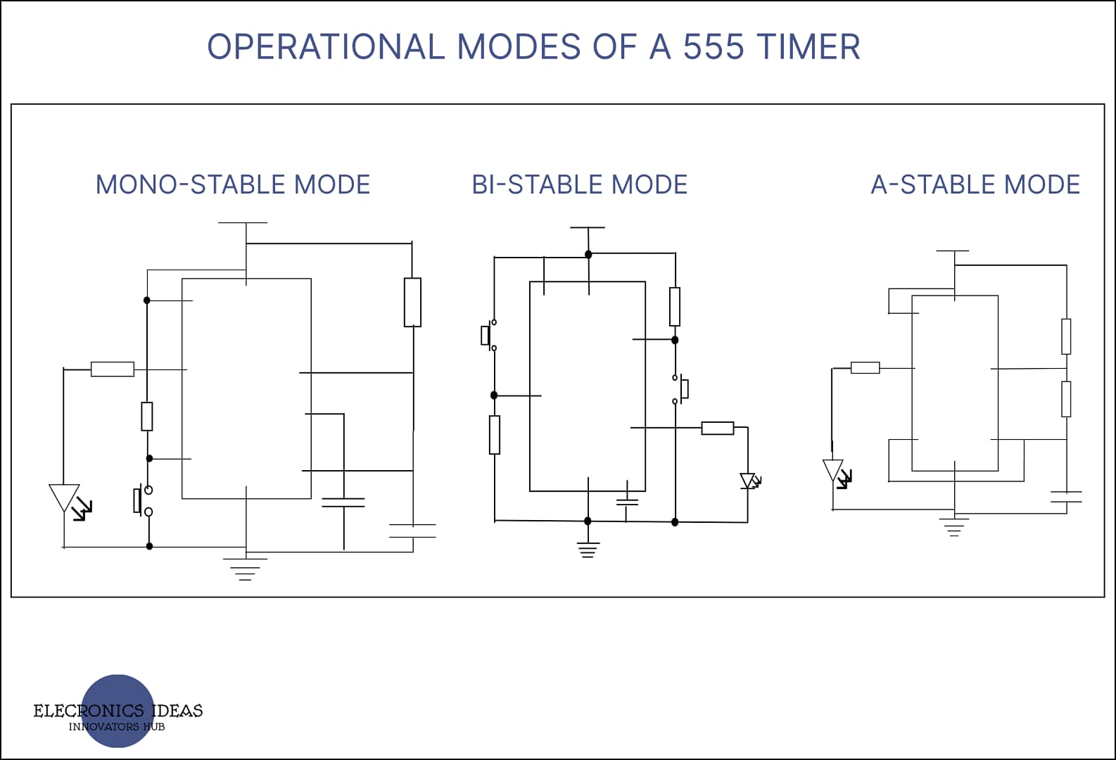
A 555 timer is an 8-pin IC and has 3 operational modes.
- A-stable mode
- Mono-stable mode
- Bi-stable mode
A-stable operational modes of a 555 timer
One of the operational modes of a 555 timer is a-stable mode. The 555 timer is used as an oscillator. In this mode, the output never stays in one state. The output continues to move from the high state to the low state until the system is turned off.
With the basic understanding of a 555 timer, we would move forward to the connection of external components on a 555 timer in a-stable mode.
First of all, pin 2 and pin 6 are connected together such that they both have the same voltage at all times. The connection is then connected to ground through a capacitor. The connection is then connected to Vcc through 2 resistors. Pin 7, the discharge pin is connected between the two resistors. We attach an LED from the output through a resistor to ground.

NOTE: If the voltage at pin 2 (trigger ) is lower than 1/3Vcc, the output would be set to high but if the voltage at pin 6 is higher than 2/3Vcc the output is reset to low. The voltage supplied to the pins is set by the capacitor voltage.
When the system is turned on if the voltage at pin 2 is lower than 1/3Vcc the output would be high turning on the LED. While the LED is on the capacitor starts charging. The capacitor voltage starts at 0V and when it reaches 1/3Vcc the output of the first comparator is set to low but the output remains high. The output remains high because the flip-flop needs to be reset before the out is set to low.
The capacitor continues charging until it crosses 2/3Vcc which sets the output of the second comparator to high. The second comparator then resets the flip-flop turning the output of the 555 timer to low. this then turns off the LED.
When the output of the 555 timer is low, the capacitor is then connected to ground through a transistor, allowing the capacitor to discharge. The second resistor prevents the capacitor from connecting to Vcc. Once the capacitor discharges to a voltage below 1/3Vcc the output of the first comparator is then set to high which in turn makes the output of the 555 timer to high.
The time it takes the capacitor to charge, that is to give out a high output is given 0.693 X (R2 + R1) X C1.
while the time it takes to discharge is given as or give a low output is given as 0.693 X R2 X C1.
Mono-stable operational modes of a 555 timer
One of the operational modes of a 555 timer is mono-stable mode. Mono-stable mode of a 555 timer is also referred to as a one-shot timer. In mono-stable mode, a signal can trigger the output of the 555 timer to go high for a period of time and then return back to low.
Let’s understand the external connection of components in mono-stable mode. We need the output of the first comparator to be low until it is triggered by a push button. To achieve this, we make use of a pull-up resistor to connect pin 2 (trigger pin) to Vcc and then we connect pin 2 to ground through a push button.
What happens here is, for the comparator to output high we need the voltage at the trigger pin to be lesser than 1/3Vcc. By connecting the trigger pin to Vcc through a resistor, the voltage at the trigger pin would be more than 1/3Vcc which would make the comparator output low. When the button is pressed pin 2 is pulled low to ground through the button, this makes the first comparator output high which sets the output of the 555 timer to high.
Once the button is released, the trigger pin automatically connects back to Vcc which sets the output of the first comparator low. since the first comparator can only set the output high, the output would remain high even after the button is released.
To reset the output to low, we need comparator 2 output to be high. To do this, we connect pin 6 to Vcc through a resistor and ground through a capacitor. Pin 7 discharge pin is also connected between the capacitor and the resistor. The capacitor can charge from Vcc and then discharge through pin 7.
To complete the circuit, an LED is connected to the output through a resistor down to ground.
Note: The time for the output to remain high is given as 1.1 X R1 X C1

Bi-stable operational modes of a 555 timer
One of the operational modes of a 555 timer is bi-stable mode. Bi-stable mode is one of the commonly used modes of a 555 timer. In bi-stable mode, two signals are used to either set the output of the 555 timer to high or reset the output of the 555 timer to low. When the output is set to high, it remains in that state until the second signal causes it to reset the output to low.
Connecting the external components for a bi-stable mode. For the output of the 555 timer to be set to high, the output of the first comparator has to be high. The positive terminal has a voltage of 1/3Vcc. For the comparator to output, high the voltage at the negative terminal has to be less than 1/3Vcc. The easiest way to do this is to connect pin 2 to ground. But since we want the output of the 555 timer to be always low unless triggered, we would make use of a pull-up resistor to connect pin 2 to Vcc and then connect pin 2 to ground through a push button switch.
The idea is that the voltage at pin 2 would always be high unless the button is pressed which then connects pin 2 to ground. This sets the output of the 555 timer to high.
To reset the output to low, Pin 6 is connected to ground through a pull-down resistor and then pin 6 is also connected to Vcc through a push-button switch. By default, the output of the second comparator would be low unless the button is pressed. When the button is clicked, the positive terminal of the second comparator receives a voltage higher than 2/3Vcc this then causes the output of the 555 timer to reset.

Related posts


