Introduction to burglar laser alarm system
Insecurity is a common problem around the world. Properties are lost to burglars that invade people’s houses and silently cart away valuable things from their victims. Anti-burglar systems have been created over the years to prevent such occurrences but burglars always develop techniques to still get into the house undetected.
Other burglar laser alarm systems have been put in place and have been serving their purposes but the major problem with them is they are very expensive and cannot be afforded or maintained by the lower class citizens. The main goal of this project is to help improve security for the lower class by providing a cheaper burglar laser alarm system that can be easily bought or implemented with cheap and readily available electronic components.
The whole system is wired around 555 timer bi-stable mode. This system uses a laser as a marker that when crossed will trigger the system to start sounding an alarm to alert the people in the house of an intruder. Since the goal of most burglars is to get into houses unnoticed, once their presence is announced they tend to run away. This system only sounds an alarm when it is triggered.
Electronic components used in this project
| S/NO | Component | Rating | Quantity |
| 1 | Battery (Vcc) | 9V | 1 |
| 2 | 555 Timer (IC) | – | 1 |
| 3 | LDR (RV1) | 100-10M | 1 |
| 4 | Resistors (R2) | 2K | 1 |
| 5 | Resistor (R1) (R3) | 1K | 2 |
| 6 | Capacitor (C1) | 0.1uF | 1 |
| 7 | Push-down switch (S2) | – | 1 |
| 8 | LED (D1) | – | 1 |
| 9 | Buzzer (Buz1) | – | 1 |
| 10 | PCB board | – | 1 |
| 11 | Breadboard | – | 1 |
| 12 | Switch (S1) | – | 1 |
| 11 | Laser pointer | – | 1 |
555 Timer: For the automated burglar laser alarm system, the 555 timer is connected in bi-stable mode. This utilizes the 555 timer as a flip-flop. The output of the 555 timer remains in one state until it is triggered to change that state or reset.

Capacitor: Pin 5 which is the control voltage of the 555 timer is connected through a very tiny capacitor (0.1uF) to ground. This capacitor acts as a filter to prevent false triggers which may be caused by wind or vibration or any other distortion.
Push button switch: A push button switch is used so that it sends a signal once, that is immediately after you click it. The button would be used to reset the automated burglar laser alarm system after it has been triggered.
LDR: LDR or light-dependent resistor is a resistor whose resistance ranges from 10M ohms to 100 ohms depending on the light intensity on it. In this system light dependent resistor (LDR) is pointed a laser beam from a laser pointer this makes the resistance of the LDR to be very low and once someone interrupts the signal or crosses through the beam, the resistance would go high and cause the system to start making an audible sound to alert people of an interruption.
Laser pointer: The laser pointer is used to point the laser beam on the LDR to keep the resistance of the light-dependent resistor LDR very low. It serves the purpose of a trap for intruders to unknowingly cross and cause the burglar laser alarm system to sound the alarm.
Block diagram of the automatic burglar laser alarm system

Circuit analysis for burglar laser alarm system
Since it’s mostly a switching system they are really not much calculation.
The recommended operational range of a LED is 20mA, to get the value of resistance to use we would use ohms law. V=IR
where V -voltage
I- Current
R – Resistance
to find R we use V/I which is 9/20mA
we get 450 ohms so the resistor to use should range from 450 ohms up. a 1K ohms resistor is used to protect the LED.
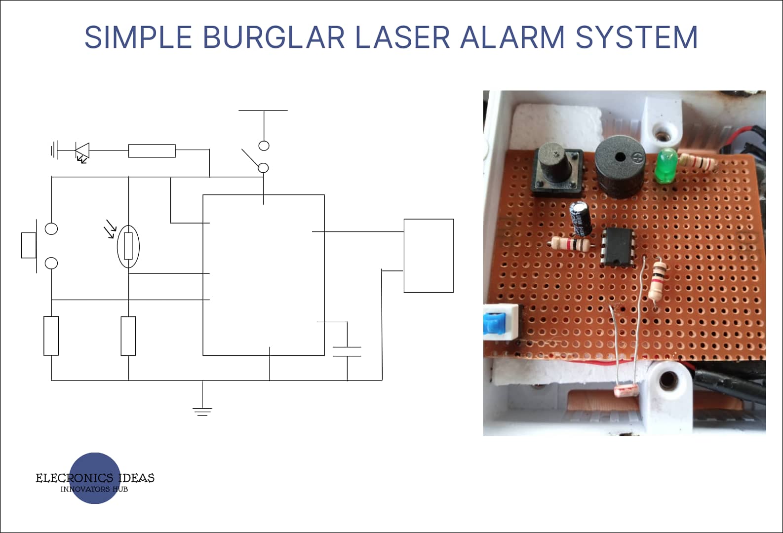
CIRCUIT DESIGN OF THE BURGLAR LASER ALARM SYSTEM

Design/ Implementation of design
The system was implemented on a breadboard and a series of tests was carried out to ensure everything worked as intended. All the tests were successful.

Final work
After all the tests were successful, the whole system was implemented on a PCB board.

Work explanation of the burglar laser alarm system
To understand how this system works it’s important to understand the bi-stable mode of a 555 timer IC. From the internal structure of a 555 timer, pin 2 is the trigger pin connected to the negative terminal of the first comparator. For the system to output high, the first comparator has to output high and the easiest way to do that is to connect the trigger to ground which is 0V.
Again, resetting the system is the job of the threshold (that is pin 6). The threshold is connected to the positive terminal of the second comparator. Refer to the internal image of the 555 timer above. For the system to reset we need the second comparator to output high, the easiest way to do that is to connect the threshold pin to the voltage source which in our case is 9V.
Relating the basic understanding of the 555 timer with our system. It’s not ideal to just connect the trigger pin to ground so the best way to do it is to place a resistor (2K ohms) between the trigger pin and ground and place an LDR between the trigger pin and Vcc. Current always flows through the path with lesser resistance. When the laser beam is resting on the LDR, its resistance tends to be very low down to about 100 ohms which is lesser than 2K ohms. The current will then flow through to Vcc which will make the first comparator output low this keeps the output of the system low.
Once the beam from the laser pointer is obstructed, the resistance of the LDR goes over 5K ohms which is more than 2K ohms. This action will make the current flow through the 2K ohms resistor down to ground this then makes the first comparator output high by so doing the system output goes high as well as making the buzzer start sounding the alarm.
To reset the system, the threshold pin is connected between a pushbutton and a 1K ohms resistor. The 1K ohms resistor is connected between the threshold pin and ground while the push button is connected between the threshold pin and Vcc. Using the same analogy of current flowing through a path with lesser resistance, the current will flow through the 1K ohms resistor to ground. To make the system reset the push button can be clicked. As the button has very low resistance the current will from through it to Vcc thereby resetting the system.
Application of the burglar laser alarm system
This system can be used anywhere applicable to increase security. It is mostly recommended for domestic purposes.
Conclusion
The system worked as expected and further research can be carried out to replace the batteries used for the system with an AC power source. The laser pointer can also be a fixed one instead of a hand-held laser pointer.
Related posts


