Introduction to water level Alarm system
Most households with overhead tanks tend to have a problem with overrunning water while pumping water into the tanks. This is a result of not knowing the quantity of water present in the tank and the whole process has to be followed manually. The person charged with the duty of monitoring the water pumping into the tank may be occupied with something else and totally forget about the pumping water.
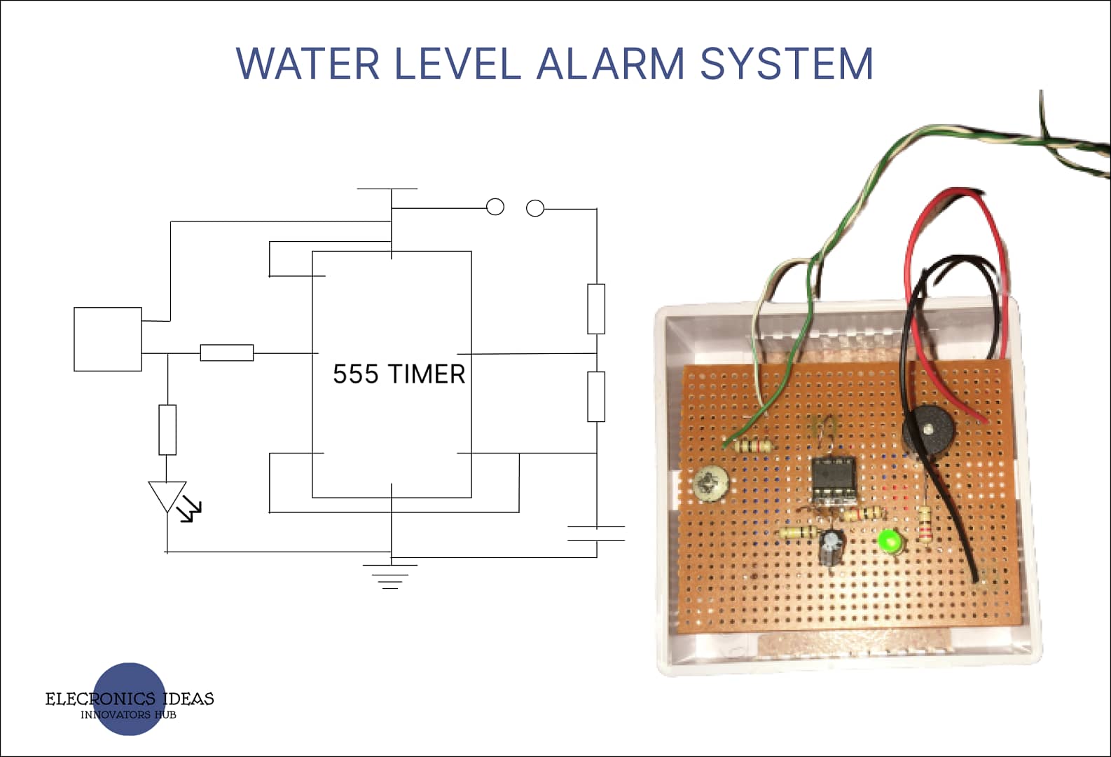
This simple water level alarm system using a 555 timer IC and powered by a 9v battery produces an audible sound when water in the overhead tank reaches a preset level alerting the household to turn off the water pump, therefore, preventing the water from overflowing. This will help save energy and prevent the overflowing of water.
The main goal of this system is to provide a cost-efficient way to monitor water in overhead tanks. The system is very easy to make as well as it is cheap and all the electronic components used can be bought quite easily either online or from an electronic shop.
Electronic components used for this project
| S/NO | Component | Rating | Quantity |
| 1 | NE555 timer (IC) | – | 1 |
| 2 | Resistors (,R2,R4) | 1K | 2 |
| 3 | Resistor (R1) | 100k | 1 |
| 4 | Resistor (R3) | 22 | 1 |
| 5 | Capacitor (C1) | 2.2uF | 1 |
| 6 | Buzzer (Buz1) | – | 1 |
| 7 | LED (D1) (Green) | – | 1 |
| 8 | Battery (Vcc) | 9V | 1 |
| 9 | PCB board | – | 1 |
NE555 timer: The 555 timer is used in a-stable mode. In this state, the 555 timer acts as an oscillator that is it changes state between high and low.

Capacitor: Capacitors are passive electronic devices that store energy while it is connected to a power source and then discharge slowly after it is disconnected from the power source. The capacitor is used in this circuit to set the timing of the output.
Resistors: Resistors limit the flow of current in a circuit.
Buzzer: The buzzer makes an audible when the water reaches a preset level in the tank.
LED: The LED is used as both an indicator.
Block Diagram of the water level alarm system

Circuit analysis for water level alarm system
The time T(ON) for the timer = 0.693*(R1+R2) *C
T(ON) = 0.693*(1k+100k)*2.2u = 0.154seconds
Therefore T(ON) = 0.154 seconds
The T(OFF) = 0.693*R2 *C
T(OFF) = 0.693*100k*2.2u = 0.152 seconds
Therefore T(OFF) = 0.152 seconds
Period of oscillation T = T(ON)+T(OFF)
T = 0.693*(R1+R2)*C + 0.693 * R2* C
T = 0.693*(R1+2R2)*C
T = 0.693(1k+200k)*2.2u = 0.305
Therefore period T = 0.306
Duty circle %D = T(ON)/T *100
%D = 0.154/0.306 * 100 = 50%
Therefore Duty circle = 50%
Frequency f = 1/T
f = 1/0.693*(R1+2R2)*C
f = 1.44/(1k + 200k) 2.2u = 3.256Hz
Therefore Frequency f = 3.256Hz
Circuit design of water level alarm system

Design/ Implementation of design
The circuit was implemented on a breadboard for further testing. In this circuit, wires are used as probes. The whole idea behind it is to close the circuit whenever water reaches the preset level.

Final work
After all series of tests had been carried out to ensure that everything works as it is supposed to, the design was then implemented on a PCB board. PCB board makes the work neater and more compact.

Work explanation of the water level alarm system
For an A-stable mode connection, both pins 2 and 6 are connected together. This means that both pins 2 and 6 will always have the same voltage. A capacitor is added connecting both to ground. The voltage supplied to pins 2 and 6 is determined by the voltage of the capacitor. Both pins are also connected to Vcc through two resistors. Between the two resistors, a connection is added to the discharge pin.
When the 555 timer is first supplied power, the capacitor is at 0 volts. Since that is lower than 1/3 Vcc, comparator 1 outputs high setting the 555 timer output high turning on the LED. The capacitor charges and when its voltage is above 1/3 Vcc, comparator 1 switches to low but the 555 timer continues to output high.
When the capacitor charges higher than 2/3 Vcc, the voltage at pin 6 causes comparator 2 to output high resetting the 555 timer output to low and the LED turns off. This also turns ON the transistor of the discharge pin. The closest resistor to Vcc prevents the capacitor prevents it from connecting to Vcc and instead forces it to connect to ground through pin 7. This makes the capacitor begin to drain. When the voltage of the capacitor is below 2/3 Vcc, comparator 2 outputs low. Dropping below 1/3 Vcc, comparator 1 outputs high causing the 555 timer output to be high and turn on the LED.
The circle of the capacitor charging to above 2/3 Vcc turns the LED off to draining below 1/3 Vcc and turning the LED on will continue as long as the circuit is supplied power.
With this in mind let’s proceed to explain this system in detail. Firstly, to ensure that our circuit outputs high when the circuit is closed we need the voltages entering pins 2 and 6 should be lower than 1/3Vcc refer to the truth table of the 555 Timer. We are using 100K ohms and 1k ohms resistors as R1 and R2 respectively such that after performing the voltage divider rule we will get 0.089V which is 9 x 1k/101k.
Note: that both pins 2 and 4 use the same voltage which is 0.089V.
This makes the first comparator connected to pin 2 output high while the second comparator connected to pin 6 output low this sets the 555 timer output high. While the output is high the capacitor continues charging until it reaches a voltage above 2/3Vcc that is 6V, then it resets the system to output low which makes ǭ to be high thereby turning the transistor into a switch since the voltage at the base of the transistor is high. This process then connects pin 7 to ground such that the capacitor discharges down to ground. After the capacitor has discharged to a voltage below 1/3Vcc it sets the output of the 555 timer back to high.
Note: In the circuit, one of the terminals of the buzzer is connected to Vcc and the other is connected to the output of the 555 timer, by this, the buzzer will only work when the 555 timers output is low. Again one of the terminals of a LED is connected to the output of the 555 timer and the other to ground so the LED will be ON when the output of the 555 timer is high. By this connection, the system demonstrates the oscillation of the 555 timer.
Application/ Uses of water level alarm system
The water level system can be used for both industrial and domestic purposes to monitor the level of water in an overhead tank to help prevent water from overrunning while pumping the water.
Conclusion
The testing and implementation of the circuit were successful but additional research can be carried out to improve the life of the system, that is the battery should be changed such that the system utilizes an AC power source.
Video demonstration of the system
Related Posts


Wow, superb blog structure! How long have you been blogging for?
you make blogging look easy. The entire glance of your site is
excellent, let alone the content!
I appreciate