Introduction to servo motors
Servo motors are electromechanical devices that are used to achieve precise control over the position, speed, and acceleration of a mechanical system. The control mechanism used by the motor is the pulse width modulation. They are commonly used in robotics, manufacturing machinery, automation equipment, and other sectors and applications that demand precise motion control.
Servo motors are made up of four (4) components that make their operation possible. These components include;
Motor: The motor is a high-performance electric motor, often a brushless DC motor or a synchronous AC motor. It provides the necessary torque and speed to drive the mechanical load.
Encoder: An encoder provides feedback on the position and speed of the motor’s shaft. It helps the control system accurately determine the current position of the motor and make necessary adjustments to achieve the desired position.
Control mechanism: The control mechanism is responsible for processing information from the encoder and generating control signals to adjust the motor’s behavior. It compares the desired position (setpoint) with the actual position (feedback) and adjusts the motor’s output accordingly.
Feedback System: The feedback system continuously measures the motor’s position and speed and sends this information to the control mechanism. This closed-loop feedback mechanism allows for precise and accurate control over the motor’s performance.
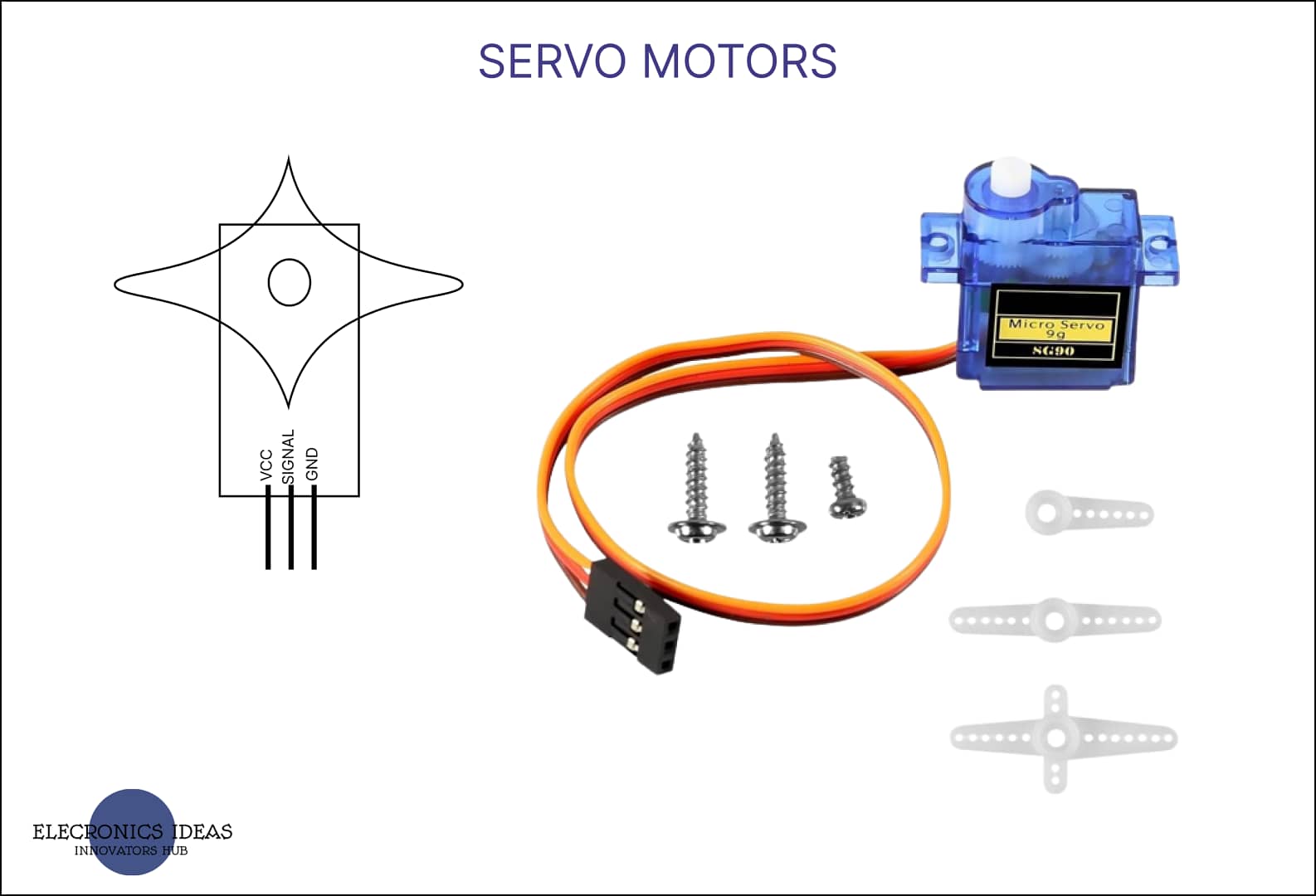
Schematics of a servo motor

How to use servo motors in Arduino projects
Servo motors are mostly used in Arduino projects. Here we will set up a simple and straightforward example that can be easily understood. In this example, we would make use of the following components:
- Arduino board (UNO R3 is used in this example)
- Servo motor (SG90)
- Jumper wires
Let’s begin with the circuit.
Connect the pin marked Vcc on the servo motor to the 5V pin on the Arduino. This servo motor can be powered by a 5v power source and an arduino can supply 5V output, so we use our arduino as our power source.
Connect the pin marked GND (ground) on the servo motor to the GND (ground) pin on the Arduino. This is to ensure that the whole system has a common ground.
Connect the signal pin on the servo motor to one of the pulse width modulation (PWM) pins on the Arduino one of the PWM pins on an arduino uno R3 is pin 9. Pulse width modulation (PWM) pins are marked with a sine wave sign in front of the pin.

Open the Arduino IDE on your computer. You can visit Arduino official website to get the arduino IDE. Ensure that all the libraries have been installed. For this example, the name of the library is Servo. Once the library is installed head back to the coding environment and import the servo library by entering the following code.
#include <Servo.h>This imports all the keywords that are related to servo motors. The next thing is to name or identify the servo motor you would be using in your project. You do that using the following code:
Servo myservo; // You can replace myservo with whatever you want to identify your servo asIn your void set up() you have to identify the pin to which the signal pin of the servo motor is connected and attach it to your servo motor. You do that using the following code in void setup()
myservo.attach(9); // Attach the servo to pin 9For this example, the signal pin of the servo motor is connected to pin 9 of the arduino.
Input the following code to the coding environment of your arduino IDE. Connect the arduino board to your computer using a USB code, select the right port, and upload the code to the board.
#include <Servo.h>

Servo myservo;  // Create a servo object

void setup() {
  myservo.attach(9);  // Attach the servo to pin 9
}

void loop() {
  myservo.write(0);   // Move the servo to 0 degrees position
  delay(1000);        // Wait for 1 second
  myservo.write(90);  // Move the servo to 90 degrees position
  delay(1000);        // Wait for 1 second
  myservo.write(180); // Move the servo to 180 degrees position
  delay(1000);        // Wait for 1 second
}
Once the code is uploaded, the servo motor will move to the specified positions (0, 90, and 180 degrees) with a one-second delay between each movement.
You can modify the code to control the servo motor’s position based on your project’s requirements. The following code function allows you to set the angle of the servo motor’s shaft between 0 and 180 degrees.
myservo.write(angle) ;// instructs the servo motor on how it should turnRemember that the specific PWM pin you use on the Arduino might vary based on your circuit connections. Always double-check your connections and make sure to use an external power supply if the servo motor draws more current than the Arduino can provide.
Signal types for servo motors
Servo motors can be controlled by both digital and analog signals. The difference between these two types of signals is that for digital signals, The servo turns based on the pre-determined angle. Once it senses a trigger signal, it turns to the angle that was set in the code.
in an analog signal circuit, the exact angle the servo motor is to turn has not been set instead, the angle is determined by a variable that can give an input analog signal such as a potentiometer. It could be that as the potentiometer is tuned, the servo motor turns an angle that corresponds to the analog signal that is given by the potentiometer.
The above example is an example of a digital signal for a servo motor. The next example is for analog signals.

#include <Servo.h>
int signal = A3;// Identifies the input analog signal
Servo myservo;  // Create a servo object

void setup() {
  pinMode(signal,INPUT);// Pointing out that its an input signal
  myservo.attach(9);  // Attach the servo to pin 9
}

void loop() {
  int position = analogRead(signal); // stores the analog signal
  int angle = map(position, 0,1023,0,180); // Marks the final angle
  myservo.write(angle); // The final position of the servo motor

}
In this second sample, we added a potentiometer. The potentiometer can give varying input signals. The first line just identifies the pin to which the wiper of the potentiometer is connected. It is connected to A3.
int signal = A3;The next code in void setup() identifies A3 (signal) as an input signal.
pinMode(signal,INPUT);This code stores the analog signal. In arduino circuits, the signal is converted to 0–1023.
int position = analogRead(signal); The mapping function takes the analog signal and draws corresponding positions for the other components. mapping function has five (5) variables, the first is the analog signal that is stored, and the next is the range between 0 – 1023 which is the range of analog signals an arduino can read. The last two are the angles the servo motors need to turn.
int angle = map(position, 0, 1023, 0, 180);Related post


I constantly emailed this webpage post page to all my friends,
since if like to read it after that my friends will too.
Thanks John
I am really impressed with your writing skills and also with the layout on your blog.
Is this a paid theme or did you customize it yourself?
Either way keep up the excellent quality writing, it is rare to see a great blog like this one these days.
Thanks Cornelius, I really appreciate it. I customized everything myself.
Hi there it’s me, I am also visiting this website daily, this website
is really good and the visitors are actually sharing
pleasant thoughts.
Thanks