Introduction to smart door system
Security is a serious problem that calls for proactive measures by all stakeholders and owners of residential buildings. Most buildings (residential and companies) do not have adequate security systems that monitor intruders and prevent unauthorized access.
To reduce this, this smart door system uses the model of keypad-enabled access and seeks to further simplify and reduce the problem of security in places where unauthorized access to companies’ materials and unauthorized access into homes is an issue. The greatest benefit of this project is its cost-efficient and does not need special knowledge to be able to execute.
The system uses common components that are readily available in the market.
Electronic components used in this project
| S/NO | Component | Rating | Quantity |
| 1 | Arduino | – | 1 |
| 2 | LCD | – | 1 |
| 3 | 4×4 keypad (KEY) | – | 1 |
| 4 | Servo motor(SER) | – | 1 |
| 5 | Power adapter | 9V, 1A | 1 |
| 6 | Buzzer(BUZ) | – | 1 |
| 7 | LEDs (D1,D2) | – | 2 |
| 8 | Resistor (R1) | 100 | 1 |
| 9 | Resistor (R2) | 220 | 1 |
| 10 | Resistor (R3,R4) | 1k | 2 |
Arduino UNO R3: is used in this smart door system. The arduino board is programmable and it has a lot of functionalities.
4 X 4 matrix keypad: The 4 X 4 matrix keypad is made of 4 rows and 4 columns which have been labeled with numbers from zero (0) to nine (9), alphabet from A to D, and two (2) special characters aesthetic (*) and hash (#). It has eight (8) connector pins which represent both the rows and the columns. For the system to identify the button that has been clicked, the intersection that is clicked allows the current flow. Let’s say you click on the number zero (0), column two (2) row four (4) allows current to flow.

Servo motor: Servo motor just like other motors can turn from 0 to 180 degrees. The basic difference is that the rotation of the servo motor can be controlled easily using a signal. for example, a signal can make a servo motor rotate just 30 degrees.

Liquid crystal Display (LCD): Is used to make some information virtual. It’s basically a screen that makes the virtualization of information easier in projects involving either arduino or raspberry pi.
Power adapter: The power adapter used is a 9V, 1A to power the arduino.
Buzzer: The buzzer used is for indication, to make an audible sound when the wrong password is entered. This helps as it can alert the household that someone is trying to gain unauthorized access to their house.
The LEDs: Are used as basic indication lights.
Block diagram of the smart door alarm system

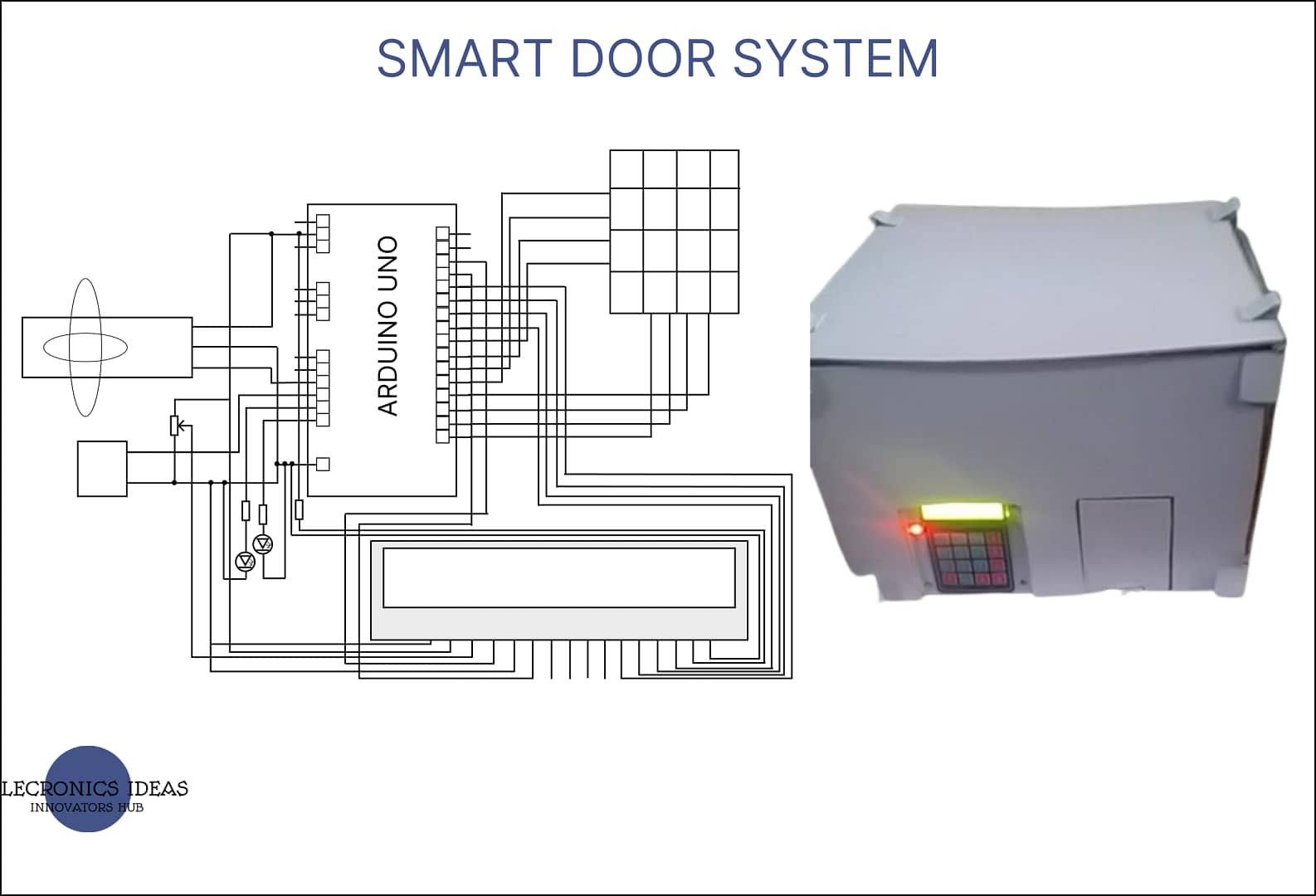
The circuit diagram of the smart door system

Circuit analysis of smart door system
A 100-ohms resistor (R1) is used to control contrast for the LCD. A 100-ohms resistor is used so the LCD would not be too dim when set to the lowest contrast.
Two (2) 1k ohms resistors (R3, R4) are used for the LEDs to limit the current passing through the LEDs. The current passing through an LED is supposed to be below 20mA. Use ohms law to calculate the current. I=V/R
Where I= current
V= Supplied voltage =5V
R = The value of the resistor to be used = 1k ohms
I=5/1000
I=5mA.
220-ohms resistor (R2) is used to limit the current flowing through the LCD. This is to prevent the LCD from damaging.
Design / Implementation of smart door design
The system was implemented on a breadboard and a series of tests were carried out to ensure everything works as expected. The code also performed as expected.
Code for the smart door system
#include <LiquidCrystal.h>
#include <Keypad.h>
#include <Servo.h>

// Pin definitions here:
#define RED_LED A0
#define BLU_LED A1
#define BUZ_PIN A2
#define SRV_PIN A3


// Global variables here:
const char *password = "2050";  // User password
const char *admnpass = "2007";  // Admin password
uint8_t keyPos = 0;       // Key position for password entry
uint8_t invalid_cnt = 0;  // Invalid entry counter
bool isAlarmed = false;   // Alarmed flag, use for alarming sound and flashing light
uint8_t currStatus = 0;   // This is for the current requested state
uint8_t prevStatus = 0;   // This holds the previous state, #### INITIALIZED THIS TO VALUE 1 #####
const byte ROWS = 4;      // 4 keypad rows
const byte COLS = 4;      // 4 keypad columns
char keys[ROWS][COLS] = { // keypad key array
{'1', '2', '3', 'A'},
{'4', '5', '6', 'B'},
{'7', '8', '9', 'C'},
{'*', '0', '#', 'D'}
};
byte rowPins[ROWS] = {7, 6, 5, 4}; // pin assignments for the keypad
byte colPins[COLS] = {3, 2, 1, 0};

// Create the objects here:
Keypad keypad = Keypad( makeKeymap(keys), rowPins, colPins, ROWS, COLS );
LiquidCrystal lcd (13, 12, 11, 10, 9, 8); // pins of the LCD. (RS, E, D4, D5, D6, D7)
Servo myservo;

// Function prototypes here:
void doAlarm();
void manageKeypad();
void manageStatus();

void setup(){
lcd.begin(16,2);         // Initialized the lcd as 16 characters by 2 lines
pinMode(RED_LED, OUTPUT); // Set the pin directions
pinMode(BLU_LED, OUTPUT);
pinMode(BUZ_PIN, OUTPUT);
myservo.attach(SRV_PIN);  // attaches the servo on pin to the servo object
myservo.write(90);        // set initial angle
manageStatus();           // Set initial lcd display
} // end of void setup()

void loop() {
manageKeypad();// Manage keypad inputs
manageStatus();           // Respond according to keypad key presses
if (isAlarmed) {          // If alarm is triggered
doAlarm();              // Make an alarm notification
}
} // end of void loop()

void doAlarm() {
tone(BUZ_PIN, 1000);        // Send 1KHz sound signal...
digitalWrite(RED_LED, HIGH);
digitalWrite(BLU_LED, LOW);
delay(150);
digitalWrite(RED_LED, LOW);
digitalWrite(BLU_LED, HIGH);
noTone(BUZ_PIN);
delay(50);
} // end of void doAlarm()

void manageStatus() {
if ( currStatus != prevStatus ) {   // check if the status is different from previous
// this is to avoid unnecessary lcd updating same display
switch(currStatus) {
case 0:                         // default screen
lcd.clear();
lcd.setCursor(0,0);
lcd.print("  Welcome  ");
lcd.setCursor(0,1);
lcd.print("Enter password");
digitalWrite(RED_LED, HIGH);
digitalWrite(BLU_LED, LOW);
prevStatus = currStatus;
currStatus = 0;
break;
case 1:                         // invalid entry
lcd.clear();
lcd.print("Invalid entry");
delay(1000);
prevStatus = currStatus;
currStatus = 0;
break;
case 2:                         // valid entry
digitalWrite(BLU_LED, HIGH);
delay(100);
digitalWrite(BLU_LED, LOW);
prevStatus = currStatus;
currStatus = 0;
break;
case 3:                         // entry verified
lcd.clear();
lcd.print("Entry verified");
digitalWrite(BLU_LED, HIGH);
delay(1000);
prevStatus = currStatus;
currStatus = 4;
break;
case 4:                         // notification for opening door
lcd.clear();
lcd.print("Opening lock");
isAlarmed = false;
tone(BUZ_PIN, 1000); // Send 1KHz sound signal...
delay(2000);
noTone(BUZ_PIN);
for (int pos = 90; pos >= 0; pos--) {
myservo.write(pos);
delay(10);
}
prevStatus = currStatus;
currStatus = 5;
break;
case 5:                         // unlocking the door lock
lcd.clear();
lcd.print(" Door open ");
digitalWrite(RED_LED, LOW);
delay(5000);
prevStatus = currStatus;
currStatus = 6;
break;
case 6:                         // warning, door will close
lcd.clear();
lcd.print(" Door closing ");
for (int i=0; i< 20; i++) {
tone(BUZ_PIN, 1000);
delay(150);
noTone(BUZ_PIN);
delay(50);
}
prevStatus = currStatus;
currStatus = 7;
break;
case 7:                         // locking the door lock
digitalWrite(RED_LED, HIGH);
digitalWrite(BLU_LED, LOW);
for (int pos = 0; pos <= 90; pos++) {
myservo.write(pos);
delay(10);
}
lcd.clear();
lcd.print("Door Closed");
delay(2000);
prevStatus = currStatus;
currStatus = 9;
break;
case 8:                         // Continues alarm
lcd.clear();
lcd.setCursor(0,0);
lcd.print("    Alarmed     ");
lcd.setCursor(0,1);
lcd.print("Enter admin pass");
prevStatus = currStatus;
break;
case 9:                         // Promotional message :)
lcd.clear();
lcd.print("JOSTUM");
lcd.setCursor(0,1);
lcd.print(" - Project 2022");
delay(3000);
currStatus = 0;
default:
break;
}
}
} // end of void manageStatus

void manageKeypad() {
char key = keypad.getKey();         // Get the key press

if (key){
if (!isAlarmed) {                 // Currently in no alarm status
if (key == password[keyPos]) {  // user password entered is still correct
currStatus = 2;               // valid entry
keyPos = keyPos + 1;          // increment the password key position
} else {                        // user password entered is incorrect
keyPos = 0;                   // reset key position, [possibility to change this to increase security
// like press something (i.e * or #) to reset counter
currStatus = 1;               // invalid entry
invalid_cnt = invalid_cnt + 1;// increment invalid counter
if (invalid_cnt == 3) {       // if 3 times invalid entry, set an alarm
currStatus = 8;             // alarmed
isAlarmed = true;
}
}
if (keyPos == 4) {              // user password entered is correct
keyPos = 0;                   // reset password key position
currStatus = 3;               // entry verified
}
} else {                          // Currently in alarmed status
// currently alarming, enter admin password to disable alarm
if (key == admnpass[keyPos]) {  // admin password entry is still correct
invalid_cnt = 0;              // reset invalid counter
keyPos = keyPos + 1;          // increment the password key position
} else {                        // admin password entered is incorrect
keyPos = 0;                   // reset key position, [possibility to change this to increase security
// like press something (i.e * or #) to reset counter
invalid_cnt = invalid_cnt + 1;// increment invalid counter
}
if (keyPos == 4) {              // admin password entered is correct
keyPos = 0;                   // reset password key position
currStatus = 0;               // reset the current status
isAlarmed = false;            // disabled current alarm
}
}
}
} // end of void manageKeypad
Final work
The system was implemented and incorporated into a building prototype.

Work explanation of smart door
The system works just like a password on your phone. It makes use of a 4 X 4 matrix keypad for input, Once the four-digit password is inputted and it is correct the Arduino makes the servo motor turn thereby opening the door. But if the password is incorrect it deducts 1 from the total attempt allowed. If the person fails to enter the correct password and the attempts allowed are finished the buzzer begins to make a sound to alert the household of a possible intruder.
Application of smart door system
This system can be modified such that can be used in homes. It is a cheaper way to increase your home security.
Conclusion
The system can be modified better such that it can also alert the house owner of a possible intruder via text message or automated call.
Demonstration video of the smart door system
Related post


Nice
Thanks
Great work
Thanks