Introduction to Decade Counter CD 4017
CD 4017 decade counter is an IC that can count from 0 to 9 in binary code. It has 10 output pins, each corresponding to a digit from 0 to 9. The output pins change state sequentially as the counter receives clock pulses from an external source. A decade counter can be used for various applications, such as displaying numbers on a seven-segment display, generating frequency-divided signals, or creating timing sequences.
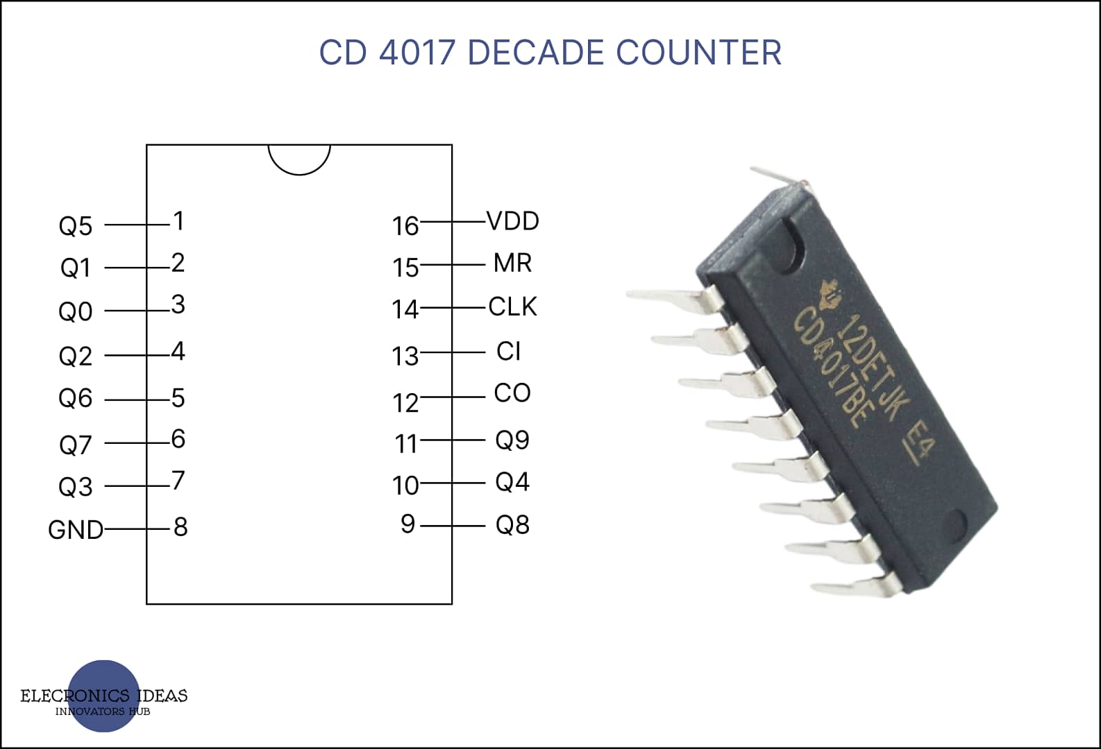
CD 4017 is a popular integrated circuit (IC) that implements a decade counter using CMOS technology. It has 16 pins, including 10 output pins (Q0 to Q9), one clock input pin (CP), one reset pin (MR), one enable pin (EN), and four power supply pins (VDD, VSS, VEE, and VPP). CD 4017 can operate with a wide range of supply voltages, from 3V to 15V. It also has low power consumption and high noise immunity. CD 4017 is a versatile and easy-to-use IC
Schematic of CD 4017

In the above schematic, each section is colored. For the section in a blue box, that is Q1 – CO are output pins. The pins in the green box are the input pins and the pins in the red box are for power.
- CO – Carry Out
- CI – Clock Inhibit
- CLK – Clock Input
- MR – Reset
- VDD – Power supply
- GND – Ground
- (Q1 – Q9) – Output pins
How CD 4017 works
CD 4017 works by receiving clock pulses from an external source, such as a 555 timer in Astable mode, and advancing its internal counter by one for each pulse. The counter can be reset to 0 by applying a high voltage to the reset pin. The clock input can be enabled or disabled by applying a low or high voltage to the enable pin. The Carry Out pin (CO) can be used to cascade multiple chips to create longer counters.
Running LED using CD 4-17
In this example, we are going to execute a simple running light system. This system involves using a 555 timer in astable mode to send the input signal. Here is a list of components that are to be used to develop this system.
- 555 timer IC (u1)
- CD 4017 (U2)
- Resistors (R1, R2, R3) 10k
- Capacitor (C1) 4.7uF
- Battery 9V
- LEDs
- Breadboard

It shows a CD 4017 connected to a 555 timer that generates a clock signal of about 1 Hz. The output pins of the CD 4017 are connected to LEDs that light up in sequence as the counter counts from 0 to 9. The reset pin is connected to a push button switch that can reset the counter to 0. The enable pin is connected to a toggle switch that can turn on or off the clock input. The carry out pin is not used in this example.
First of all, we need to set the 555 timer in Astable mode with the right signal timing. To know both the On and Off time of an Astable mode you just need to input the values of resistors and capacitor to get the timing.
For on time (Ton)
TON = (R1 +R2) X 0.693 X C1
TOFF = R2 X 0.693 X C1
Use the above formula to calculate the timing when the output signal of the 555 timer will be high or low and make the necessary adjustments to suit what you want. You can read more from our post on 555 timer. You can also use this free tool to calculate the timing.
Moving to the Counter IC, We connected the Reset pin, Gnd pin, and Carry inhibit to ground. We are not using the carry out pin. The VDD is connected to the power supply which in this example is 9V. Q0 – Q9 pins are connected to LEDs and then through a resistor to ground.
Applications and uses of CD 4017
The CD4017 has many applications in low-range counting and sequencing circuits. Some examples are:
- LED chaser: A circuit that makes LEDs blink in a pattern, such as a circular or linear motion. The CD4017 can be used to control the LEDs by connecting them to the output pins. The clock pulses can be generated by another IC, such as a 555 timer, or by a switch.
- Frequency divider: A circuit that reduces the frequency of an input signal by a factor of 10 or 8. The CD4017 can be used to divide the input signal by connecting the clock input to the signal source and the output to a load, such as a speaker or an oscilloscope. The output signal will have the same shape as the input signal, but with a lower frequency.
- Binary counter: A circuit that converts decimal numbers into binary numbers, which are represented by 0s and 1s. The CD4017 can be used to convert numbers from 0 to 9 or from 0 to 7 into binary by connecting the output pins to LEDs or display segments. The clock pulses can be generated by a push button or a switch.
- Random number generator: A circuit that produces random numbers from 0 to 9 or from 0 to 7. The CD4017 can be used to generate random numbers by connecting the output pins to LEDs or display segments. The clock pulses can be generated by a noise source, such as a microphone or a radio receiver.
Related post


