Introduction to simple AC to DC charger
In electronics projects, a charger is important as it is used to charge up rechargeable batteries. The processes involved in developing a charger include converting AC voltage to DC voltage. The process is pretty straightforward.
How to construct a simple charger
To construct a simple 9V charger, the following components are going to be used;
| S/NO | Hardware componet | Value | QTY |
| 1 | Stepdown Transformer | (220V-12V)AC | 1 |
| 2 | Diodes | 2N2222 | 5 |
| 3 | Capacitor | 1000uF | 1 |
| 4 | Voltage Regulator | LM7812 | 1 |
| 5 | Resistor | 4.7ohms | 1 |
| 6 | LED | – | 1 |
| 7 | Resistor | 10kohms | 1 |
12V stepdown transformer: The primary purpose of a step-down transformer is to lower the voltage supplied to it. In the case of a 12-volt step-down transformer, it takes in a higher voltage, let’s say 220V, and outputs a consistent 12-volt voltage. The transformer only works with AC voltage. That is to say, It takes 220V AC in the input terminals and outputs 12V AC from the output terminals.
Rectifying diodes: Rectifying diodes, often simply referred to as diodes, are semiconductor devices with a fundamental role in electrical circuits. They primarily serve the purpose of converting alternating current (AC) into direct current (DC) by allowing current to flow in only one direction.
Capacitor: Capacitors are passive electronic components that store and release electrical energy in the form of an electric field. They play essential roles in various electronic circuits and have several characteristics and applications. They smooth out voltage fluctuations and reduce noise in power supplies and signal lines in AC to DC conversion.
12 V Voltage Regulator: 12-volt voltage regulators, are electronic components used to maintain a steady and stable output voltage of 12 volts, regardless of fluctuations or variations in the input voltage. The primary function of a 12V voltage regulator is to ensure that the output voltage remains at a constant 12-volt DC, even when the input voltage may vary or fluctuate. This regulation is crucial for powering sensitive electronic devices that require a stable voltage supply. They can often handle input voltages ranging from around 14-35 volts, making them suitable for a wide range of applications.
Resistor: The resistor referred to here is a high-wattage resistor with low resistance. High-watt resistors with low resistance values are used in applications where high power dissipation and precise resistance values are required. They serve as load resistors, current sensing resistors, or voltage divider components in various electronic circuits. To handle high power levels, these resistors are built with robust materials and construction techniques. They often have large ceramic or wire-wound elements to distribute heat effectively. The choice of materials and design ensures durability and reliability. They are used in power supplies, voltage regulation circuits, motor control systems, and inverters. You can read more here.
LED: The LED is used as an indicator to show the charger is active.
Resistor: The resistor is used to limit the current entering the LED to prevent the LED from being damaged.
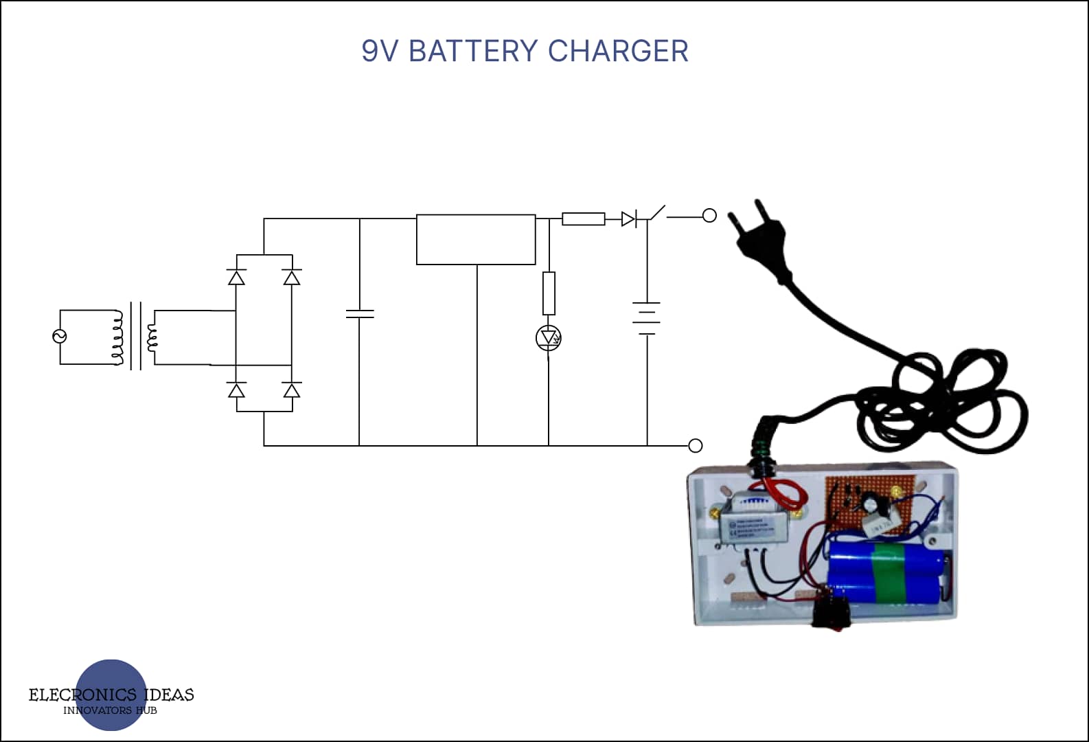
Circuit diagram for 9V charger

How the charger works
First of all, the transformer steps down the voltage from 220V AC to 12 V AC. The 12V AC is then passed through rectifying diodes which convert the the 12V AC to 12V DC. A filtering capacitor is then connected to the system to filter out any AC component that is left. The capacitor is usually a high-value capacitor. The filtered DC voltage is then passed through a 12V voltage regulator to ensure the voltage remains stable. A limiting resistor is then connected to the output of the regulator and to an LED to serve as an indicator that the system is active.
A high-power resistor is also connected to the output of the voltage regulator to a diode which prevents the backflow of current from the battery. The anode of the diode is then connected to the anode of the battery and the negative terminal of the battery is connected to the ground of the system. A switch is then attached from the battery to the output of the charger.
Note: You can make other chargers with this list above. The only thing to consider before designing the charger is that the transformer voltage and the voltage regulator should be higher than the maximum battery capacity of the battery. For a charger that can charge a 12V battery you need to change the transformer to a 15V transformer and the voltage regulator has to be a 15V regulator as the maximum capacity of a 12V battery is 14V.
Final images after implementation


Video demonstration
Related post


Howdy! Someone in my Facebook group shared this site with us so
I came to take a look. I’m definitely enjoying the information. I’m book-marking
and will be tweeting this to my followers! Exceptional blog and amazing style and design.
Thanks Andre, I really appreciate