I2C communication refers to the transfer of data between two devices. It stands for Inter-Integrated Circuit. It is a protocol that aids the communication/data transfer between two microcontrollers or components. For example, I2C technology is used in robotics to control all the different parts and aspects of the robot. Most electronic devices today make use of I2C protocol to operate.
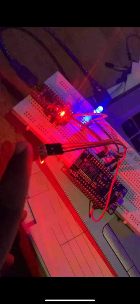
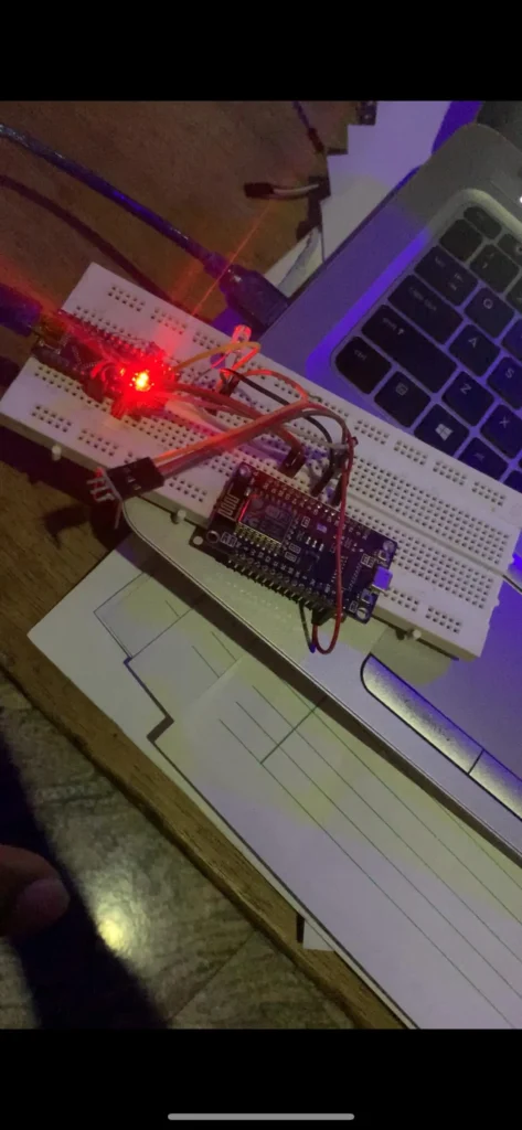
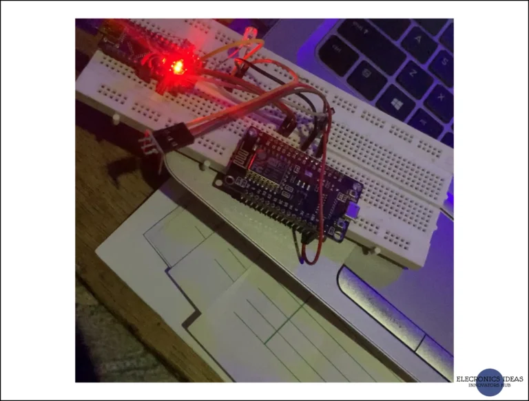
In this study, we will limit our study to communication between two microcontrollers (Arduino Nano and ESP8266). We will use a TTP223 capacitive touch sensor connected to an ESP8266 to turn on an LED connected to Arduino Nano. The idea is to use I2C communication to transfer data between both microcontrollers.
Set up of Microcontrollers
In I2C communication, the Wire Library will be used. The Wire Library is a preinstalled library in Arduino IDE that enables I2C communication. It uses a master and slave, that is, one of the microcontrollers is configured as a master and the other as a slave.
The master is the main controller. In our case, the ESP8266 will be the master as we plan to control the output on the Arduino from the input of the ESP. When the button connected to the ESP is clicked we will send the data to the slave which then executes the instructions. The master may be connected to an LCD to display sensor readings.
The slave receives instructions from the master and executes them accordingly. The slave can be connected to a sensor or network of sensors. The readings from these sensors will be sent to the master for further processing.
Some I2C connections are just for one-way communication while others are for both ways. The main difference lies in the code and the use case of the devices
Circuit Diagram
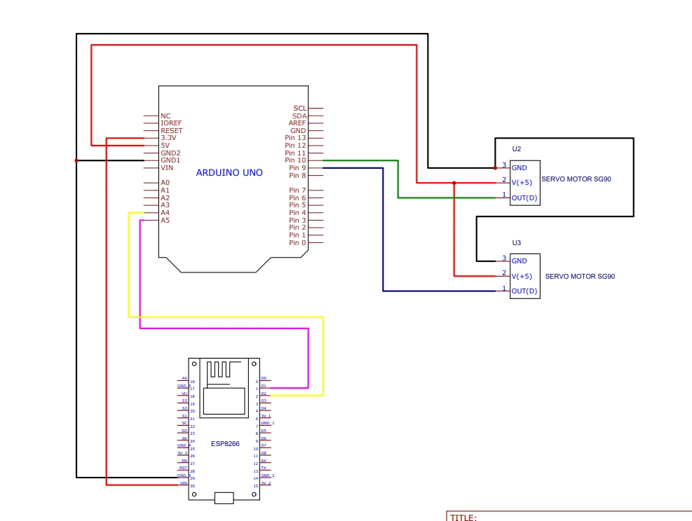
After implementing the above circuit, the next step is programming the microcontrollers. This is a simple implementation circuit for I2C communication.
Programming the master microcontroller
Upload the following code to your ESP8266 board.
#include <Wire.h>

#define SLAVE_ADDR 9

int but = 13;
int state;

void setup() {
  Serial.begin(115200);
  Wire.begin();
}

void loop() {
  Serial.println("hello");
  Wire.beginTransmission(SLAVE_ADDR);
  state=digitalRead(but);
  Wire.write(state);
  Wire.endTransmission();
}
In the above code, we declared that the button is connected to GPIO13(D7). We set up a slave address as 9. We used the state variable to store the current state of the button, we sent what is stored in the variable to the slave using the Wire.write function. The serial monitor is used for troubleshooting, in case of any error we will be able to trace the issue more easily.
Programming the Slave
Upload this code to the Arduino Nano as the system’s slave.
#include <Wire.h>

#define SLAVE_ADDR 9

int led = 7;

int rd;
int stat;

void setup(){
  pinMode(led,OUTPUT);
  Wire.begin(SLAVE_ADDR);
  Wire.onReceive(receiveEvent);
  Serial.begin(9600);

}

void receiveEvent(){
  rd = Wire.read();
  Serial.println(rd);
  Serial.println("hello");
}

void loop(){
  if(rd==1){
    digitalWrite(led,HIGH);
  }
  else{
    digitalWrite(led,LOW);
  }
}
We connected the LED on D7 of the Arduino Nano. We declared a variable rd which will store the data received via the I2C communication from the ESP8266. The onReceive function receives data and stores it in the rd variable. In the loop function, we use a simple if statement to turn on the LED using a simple comparison
