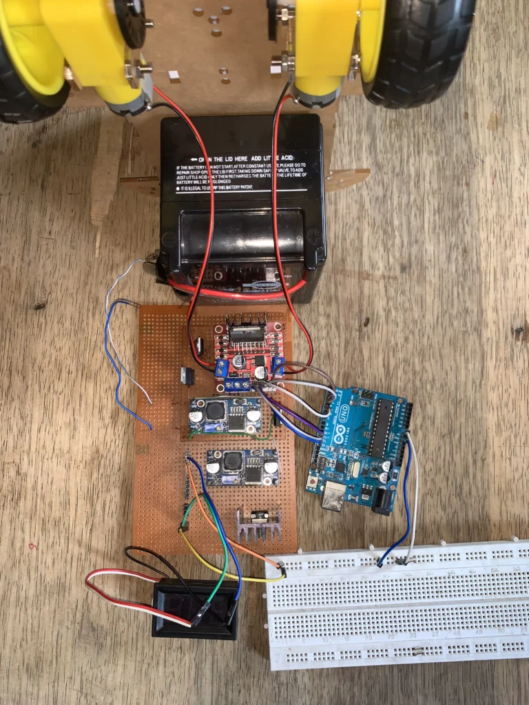
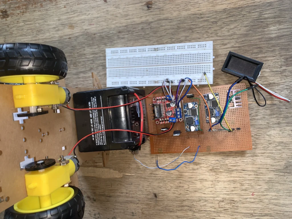
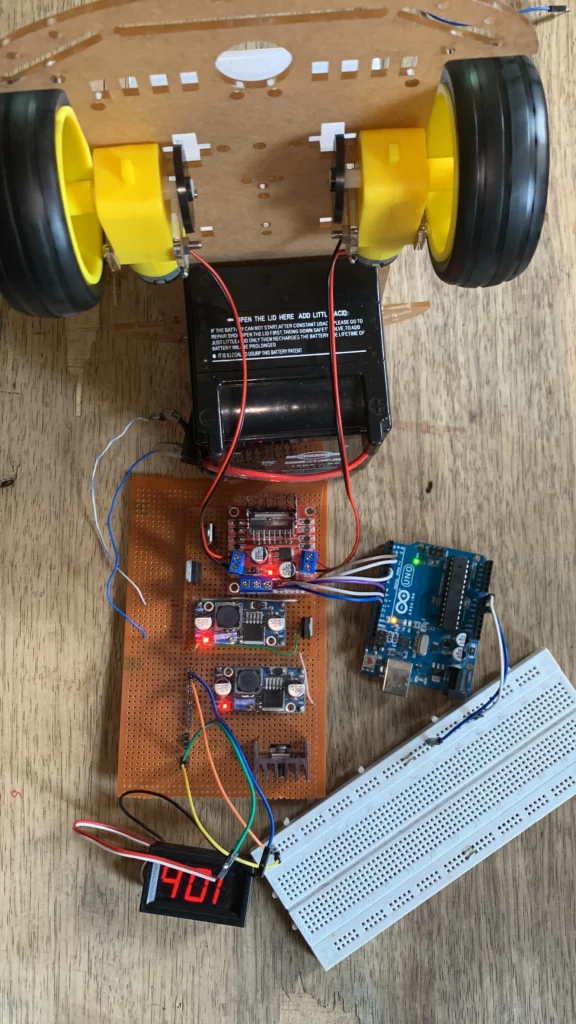
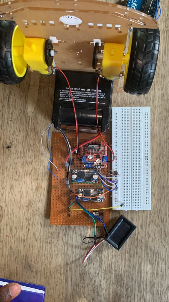
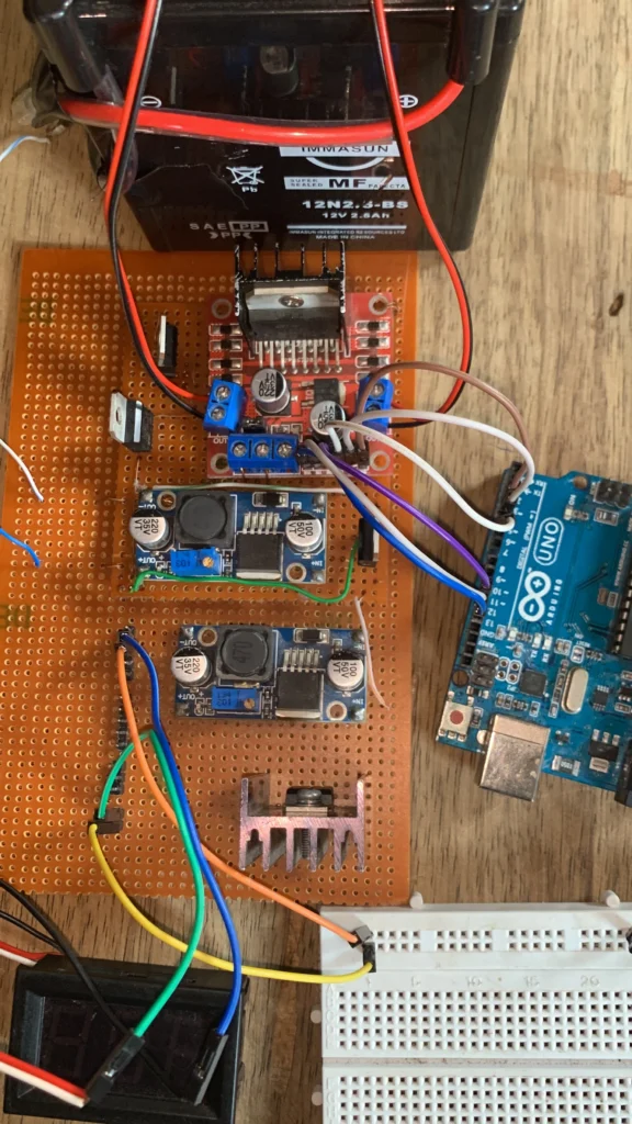
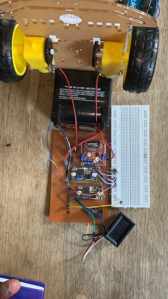
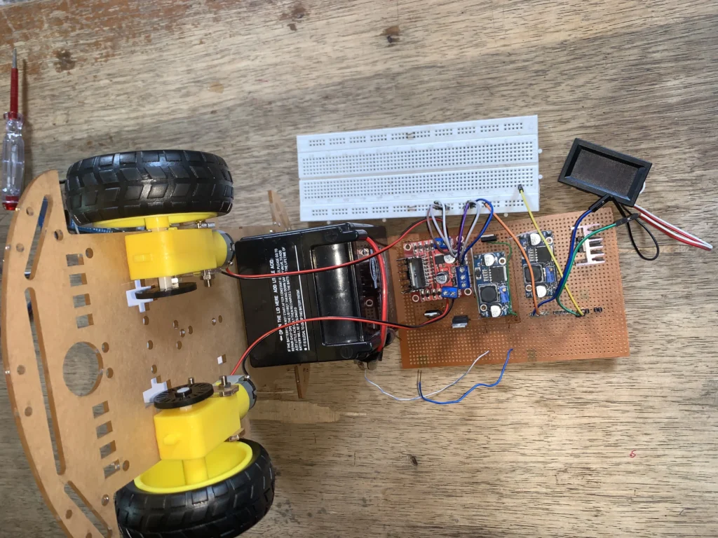
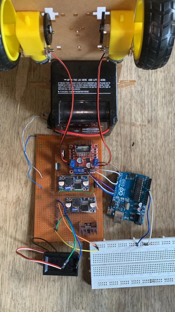
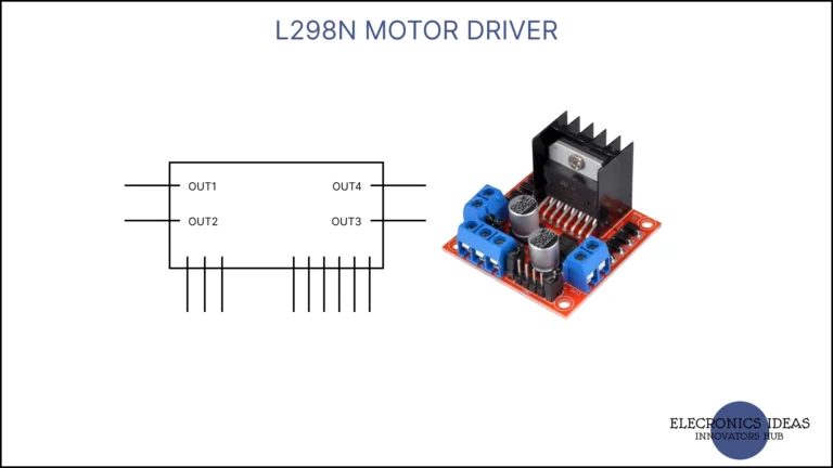
The L298N dual H-bridge motor driver is among the most popular DC motor drivers. It features a simple interface and uses fewer pins to connect to the microcontroller. Its method of integration allows it to support a wider range of microcontrollers.
In this practice, we will focus more on understanding how to use the L298N in Arduino projects
L298N Pinout
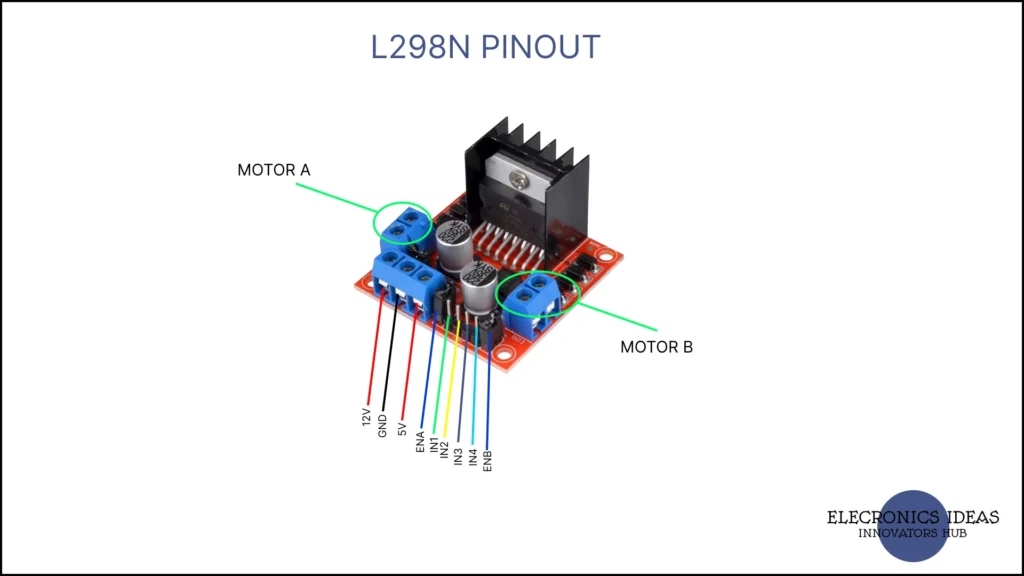
12V Pin: This is the input voltage for the DC motor connected. The input voltage can range from 5V to 35V. There is usually a 2V voltage drop, that’s to say if the input voltage is 12V the output the motor will receive will be 10V.
GND: This is to be connected to the system’s ground for a common ground.
5V: In most cases, this pin acts as an output pin that can power 5V components in the system. In some cases where the number is removed, it acts as an input to power the motor driver. This is when more than 12V is supplied to the motor driver to save the inbuilt 5V regulator from damage.
EnA and EnB: This pin activates the motor output by applying 5v across using the jumper. PWM signal can also be applied to vary the speed of the motor.
In1, In2, In3, In4: These pins move the motor connected to the motor driver. Applying 5V and ground to these pins alters the outcome of the motor.
Motor A and Motor B: This is where the motors are attached. When using two motors connect one on motor A and the other on motor B. When using four motors connect two on motor A and the other two motors on motor B. The connection is a parallel.
Operation of the L298N motor driver
The table below shows the basic movement of the motor connected to the motor driver. This table is based on applying 5V to the respective pins that indicate HIGH and GND to the pins marked with LOW.
This can also serve as a basic if you are using an Arduino to control the operation of the motor driver. ENA and ENB pins are used to manipulate the speed of the motors using code. Remove the jumper on both pins to provide more flexibility.
| FORWARD | REVERSE | LEFT | RIGHT | |
| IN1 | HIGH | LOW | HIGH | LOW |
| IN2 | LOW | HIGH | LOW | HIGH |
| IN3 | HIGH | LOW | LOW | HIGH |
| IN4 | LOW | HIGH | HIGH | LOW |
Using 5V and ground to control the output of the L298N
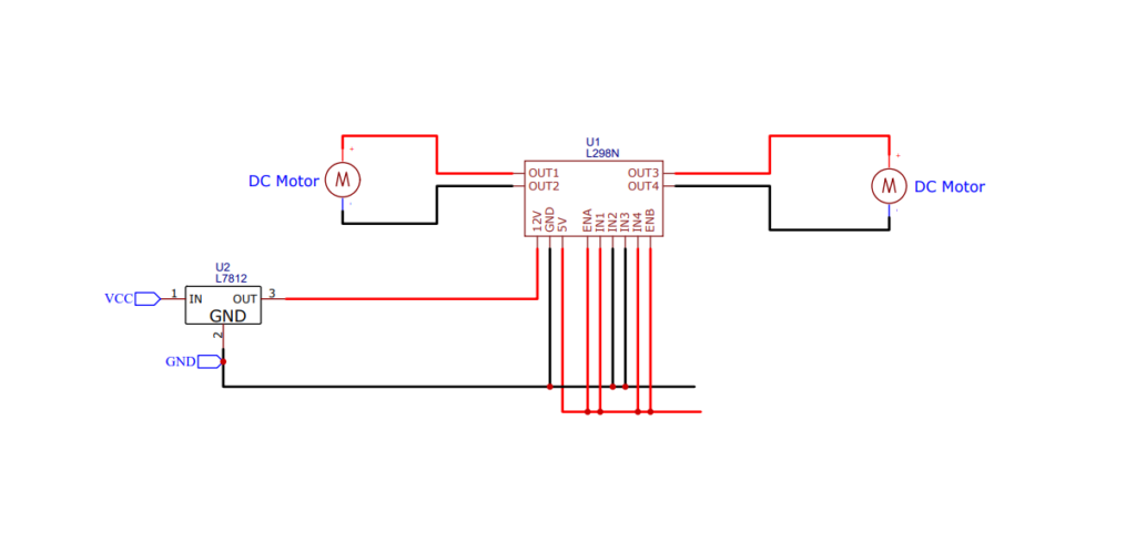
Using the table above it can be derived that motor A will move forward while motor B will reverse.
Using an Arduino to control an L298N motor driver
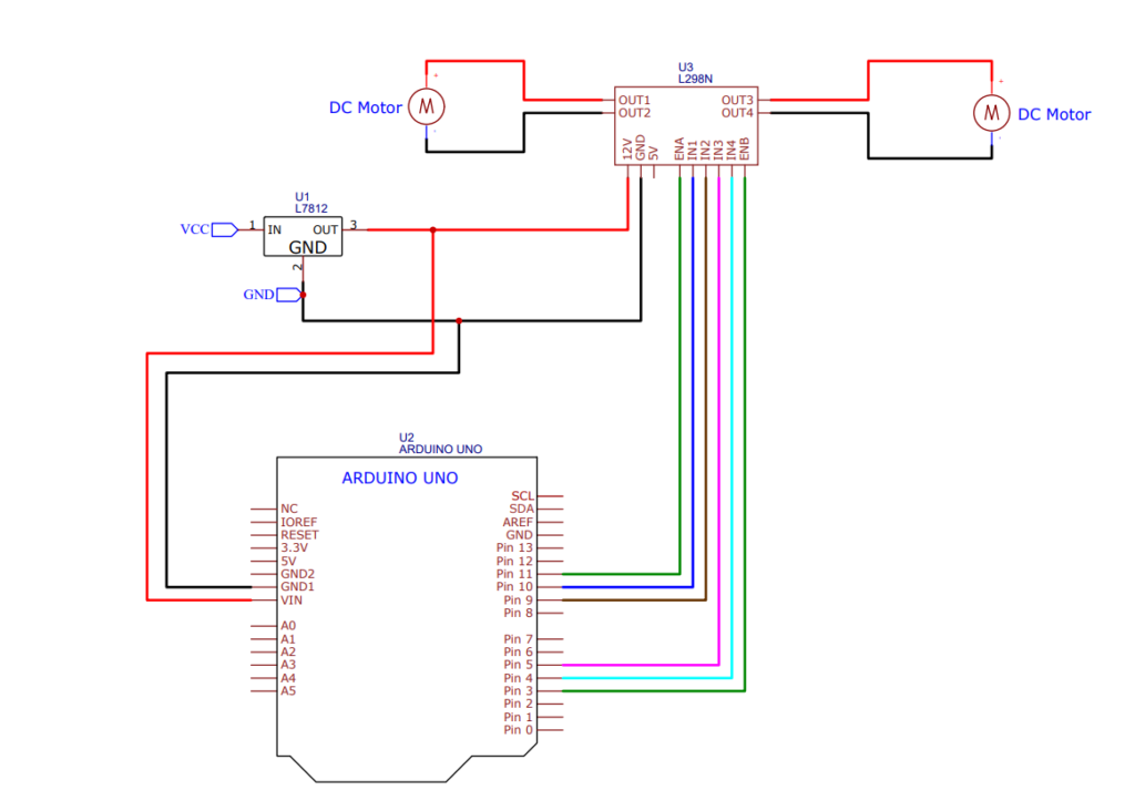
We will make a simple code to move the motors forward for 5 seconds and then reverse for 5 seconds. The circuit diagram below connects the L298N motor driver to your Arduino.
int enA =11;
int in1 = 10;
int in2 = 9;
int enB =3;
int in3 =5;
int in4=4;

void setup() {
    pinMode(enA,OUTPUT);
    pinMode(enB,OUTPUT);
    pinMode(in1,OUTPUT);
    pinMode(in2,OUTPUT);
    pinMode(in3,OUTPUT);
    pinMode(in4,OUTPUT);
}

void loop(){
    analogWrite(enA,100);
    analogWrite(enB,200);

    digitalWrite(in1, HIGH);
    digitalWrite(in2, LOW);
    digitalWrite(in3, HIGH);
    digitalWrite(in4, LOW);
    delay(5000);


    digitalWrite(in1, LOW);
    digitalWrite(in2, HIGH);
    digitalWrite(in3, LOW);
    digitalWrite(in4, HIGH);
    delay(5000);

}
