A typical I2C system consists of two separate components or microcontrollers between which we intend to enable data transmission. The I2C system is handy in electronics design as it can facilitate communication between as many as 119 components. The I2C system is made up of 4 pins, they are power (Vcc), ground, SCL, and SDA pins.
You can connect multiple slaves to a single I2C bus, to communicate with a particular slave all you have to do is add the slave’s address.
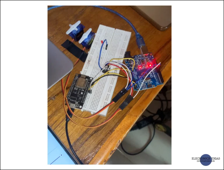
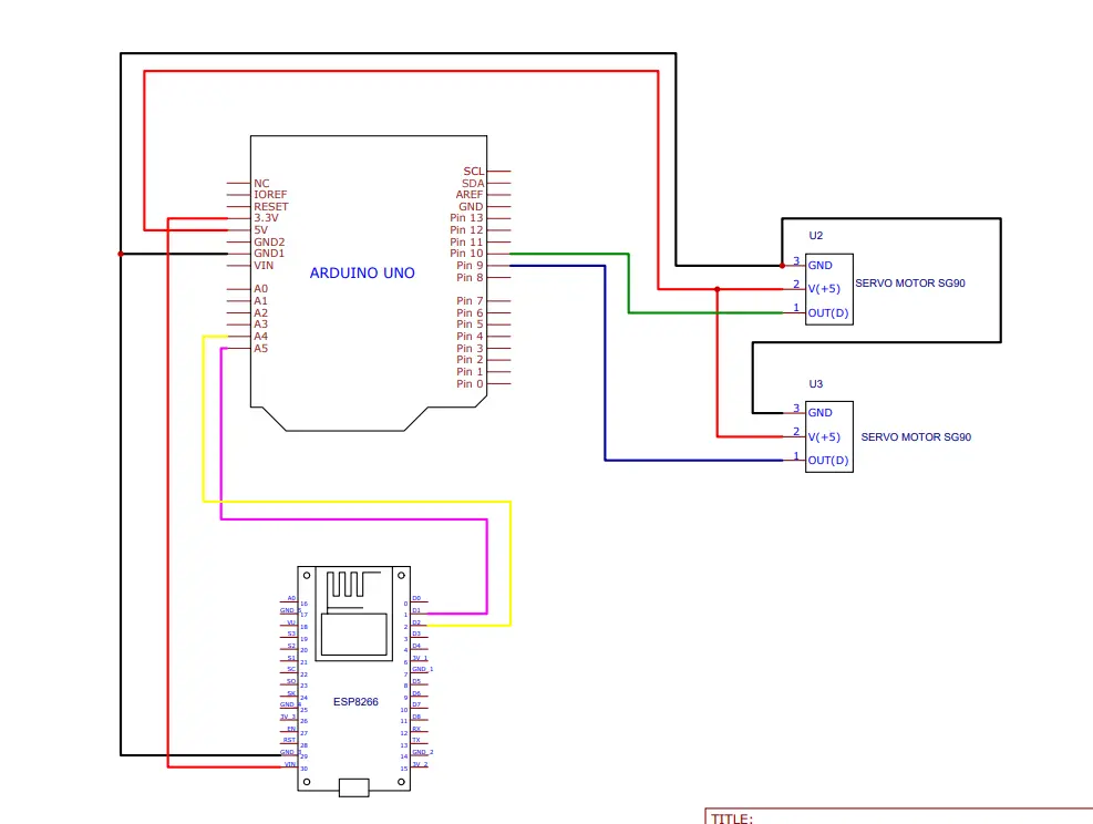
In this particular exercise, we will control two (2) separate devices (servo motors) connected to a single slave device (Arduino Uno). The master in this system will be an ESP8266 connected to Blynk Iot. We are using two slider widgets to control the servo, One for each.
Setting up the Slider widgets in Blynk IoT
Using the desktop version, open the Blynk cloud dashboard. NOTE: You have to create a Blynk account to access their services. The free version is enough for most projects.
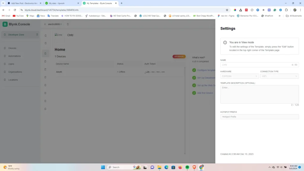
First, configure the template. Under Developers zone > My templates and create a new template. Select ESP8266 under Hardware and Wifi under Connection Type.
The next step is to create your Datastreams. Click on + New Datastream and select Virtual PIN, you will be prompted with a pop-up to fill in the details. Since we are working with a servo motor, after giving it the name you want select a virtual pin from V1 – V255. Under Data type select Integer, set units to none and select the min, max and default values (0-180).
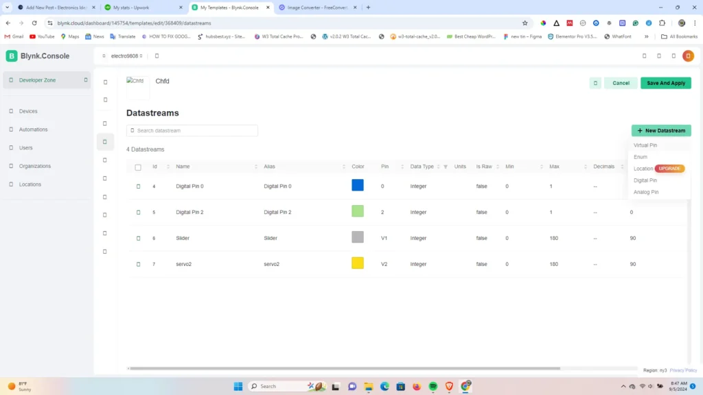
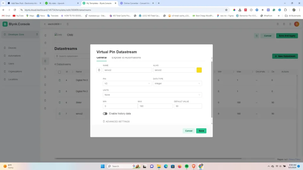
Note: I am using V1 for the first servo and V2 for the second servo.
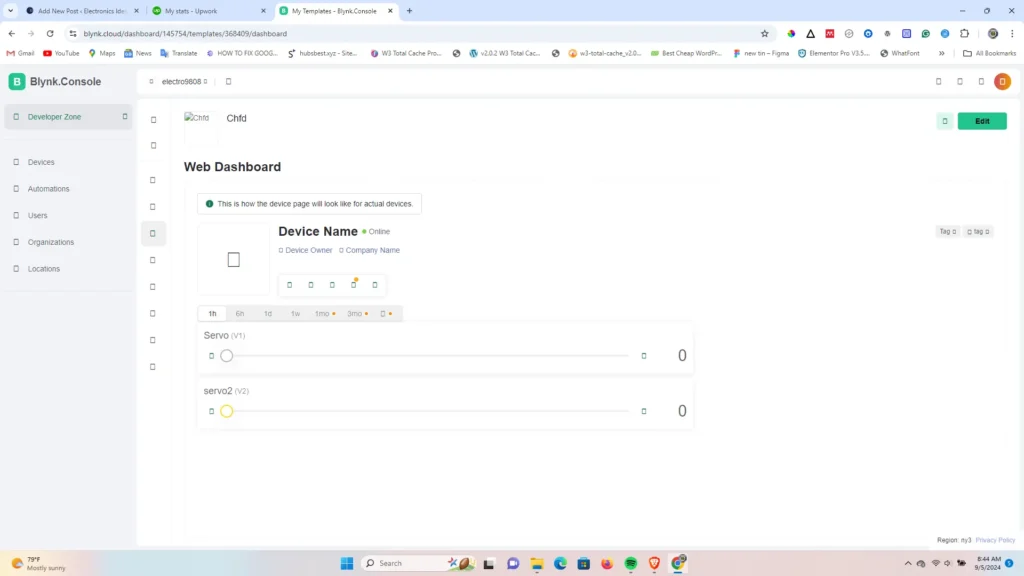
Setting up the dashboard next, drag and drop two slider widgets and connect them to the created datastreams(V1 and V2).
Circuit diagram of the I2C system
Programming the Master of the I2C system
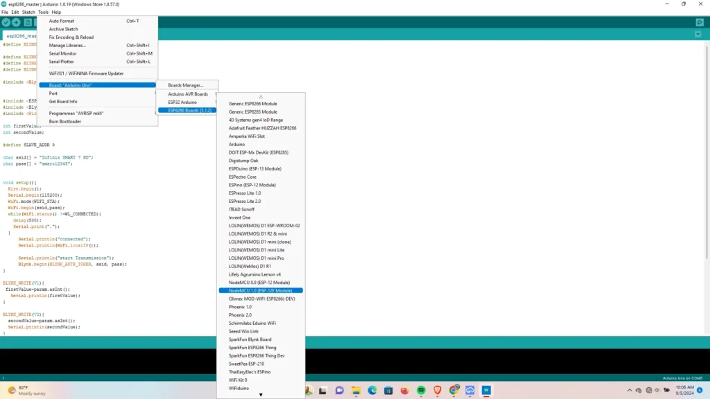
The master of the I2C system is the ESP8266, our goal is to use the widgets in the Blynk IoT system as the input signal to control the output on the slave. Open your Arduino Ide, paste the following code and upload it to the ESP8266 board.
#define BLYNK_PRINT Serial

#define BLYNK_TEMPLATE_ID "TMPL21PrvggI0"
#define BLYNK_TEMPLATE_NAME "Chfd"
#define BLYNK_AUTH_TOKEN "_L2bboj-3o65oVX6ueHH_yu3dVJzozpN"

#include <Blynk.h>


#include <ESP8266WiFi.h>
#include <BlynkSimpleEsp8266.h>
#include <Wire.h>

int firstValue;
int secondValue;

#define SLAVE_ADDR 9

char ssid[] = "Infinix SMART 7 HD";
char pass[] = "smart12345";


void setup(){
  Wire.begin();
  Serial.begin(115200);
  WiFi.mode(WIFI_STA);
  WiFi.begin(ssid,pass);
  while(WiFi.status() !=WL_CONNECTED){
    delay(500);
    Serial.print(".");
  }
      Serial.println("connected");
      Serial.println(WiFi.localIP());

      Serial.println("start Transmission");
      Blynk.begin(BLYNK_AUTH_TOKEN, ssid, pass);
}

BLYNK_WRITE(V1){
 firstValue=param.asInt();
   Serial.println(firstValue);
}

BLYNK_WRITE(V2){
  secondValue=param.asInt();
  Serial.println(secondValue);
}

BLYNK_CONNECTED(){
  Blynk.syncVirtual(V1);
  Blynk.syncVirtual(V2);
}

void loop(){

  Wire.beginTransmission(SLAVE_ADDR);
  Wire.write(firstValue);
  Wire.write(secondValue);
  Wire.endTransmission();
  Blynk.run();

}
Copy the following code from your Blynk dashboard under the Template and paste it into the code.
#define BLYNK_TEMPLATE_ID "TMPL21PrvggI0"
#define BLYNK_TEMPLATE_NAME "Chfd"
#define BLYNK_AUTH_TOKEN "_L2bboj-3o65oVX6ueHH_yu3dVJzozpN"
Change the SSID and password to match your home network
char ssid[] = "Infinix SMART 7 HD";
char pass[] = "smart12345";
Programming the slave of the I2C system
The slave of the system is an Arduino Uno with two servo motors connected to pins 9 and 10. Code the following code and upload it to the board. Ensure to select Arduino Uno under the board and the right com port.
#include <Servo.h>
#include <Wire.h>


#define SLAVE_ADDR 9
Servo servo1;
Servo servo2;

int rd1;
int rd2;

void setup() {
 servo1.attach(9);
 servo2.attach(10);
 Serial.begin(9600);
 Wire.begin(SLAVE_ADDR);
 Wire.onReceive(receiveEvent);
 Serial.println("Active");
}


void receiveEvent(){
 rd1= Wire.read();
 rd2=Wire.read();

}


void loop() {
 servo1.write(rd1);
 Serial.println(rd1);
 delay(20);
 servo2.write(rd2);
 Serial.println(rd2);
 delay(20);

}