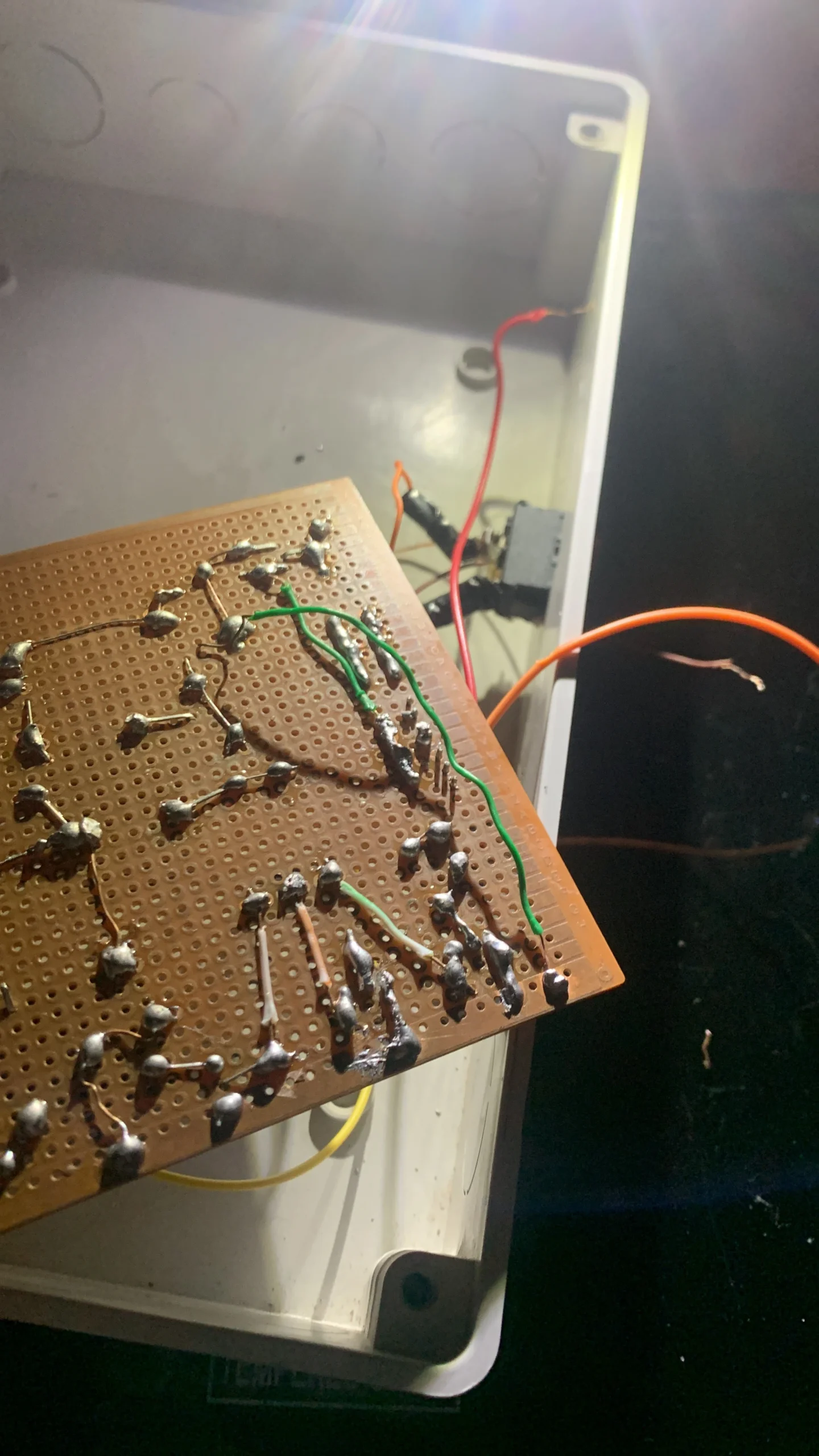
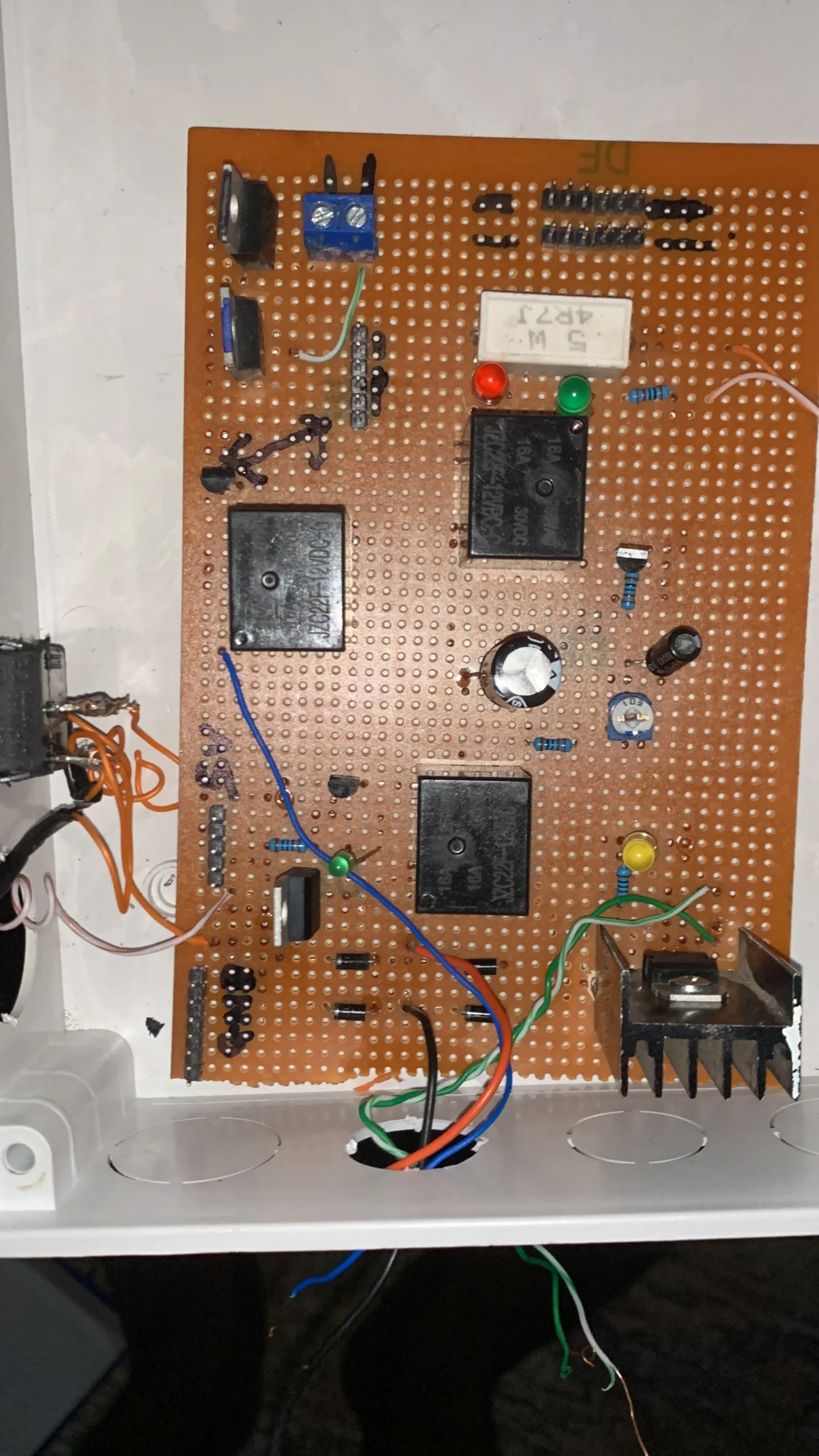
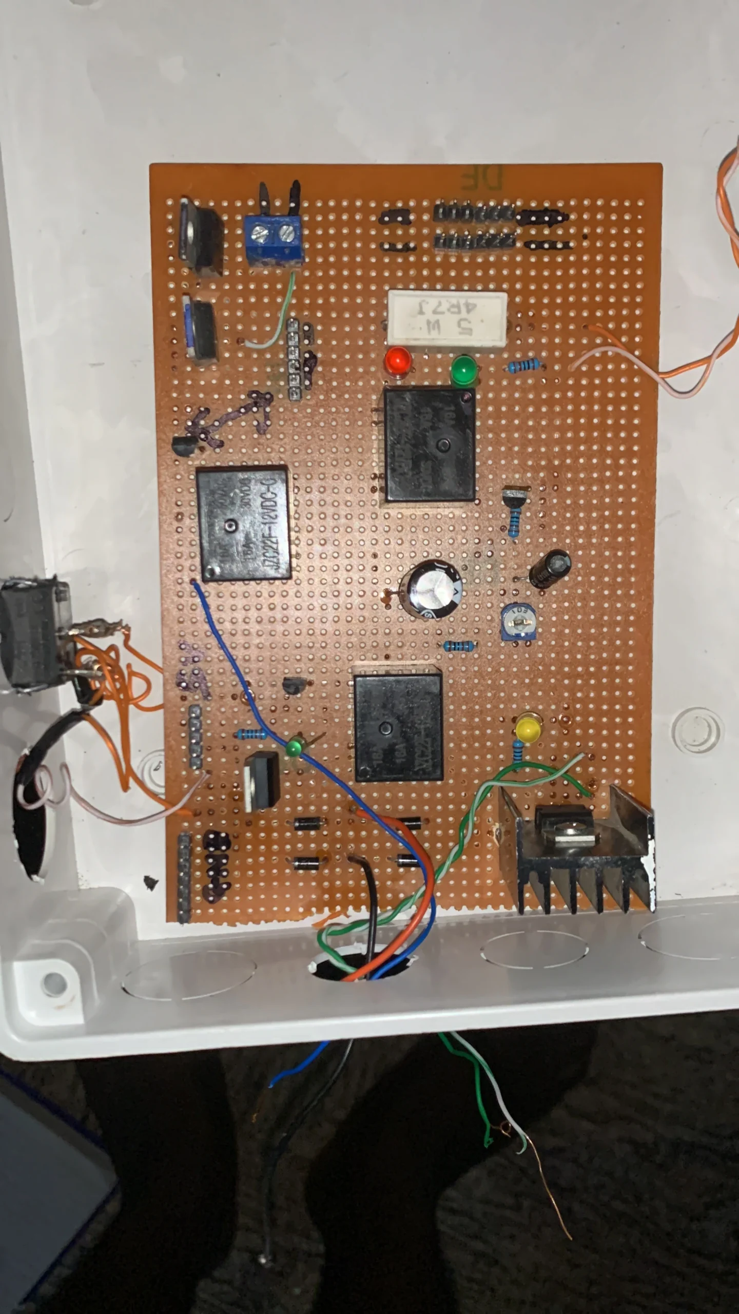
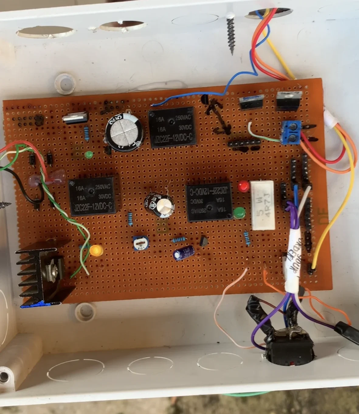
In this project, we will design a dual power source charger. This charger uses power from the electricity grid and solar power. The system prioritises the electricity grid over solar. In simple terms, if both sources are available, the system will automatically select the electric grid.
This charger features two main characteristics: an automatic power selector and an automatic cut-off when the battery is full.
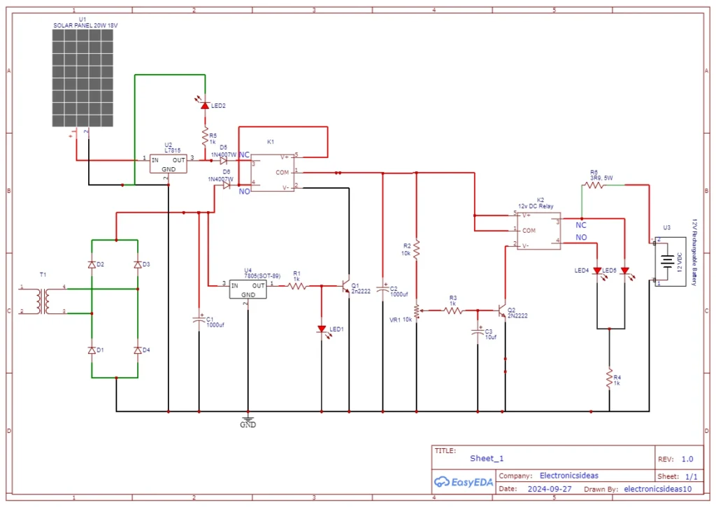
Circuit Diagram for Dual power source charger
Circuit Explanation for Dual Power Source Charger
Let’s begin with the automatic power selector. In this section, the system auto-selects the available power supply. The grid is connected to the NO(normally open) pin on the relay while the solar is connected to the NC (normally closed) pin. By default, solar power will be output as long as there is no power supply from the grid.
Once power comes on the grid, the transistor on the negative terminal of the relay will switch on the relay therefore moving the power supply from solar to the grid. The grid section of the system has a rectifying circuit and a filtering capacitor to ensure every AC component is removed.
The 5v regulator acts as a signal to turn on and off the transistor that is connected to the relay. This acts as the selector switch. The system will always select the grid if both sources of power are available.
The auto-cut-off of the charger is controlled by a relay that switches open when the battery is fully charged. This is similar to the previous chargers we have designed before.
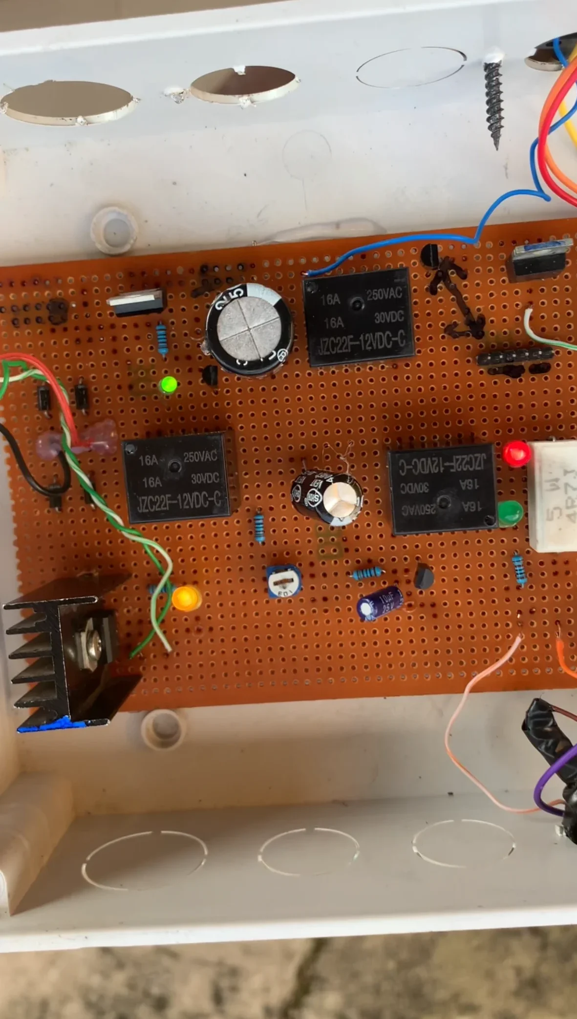
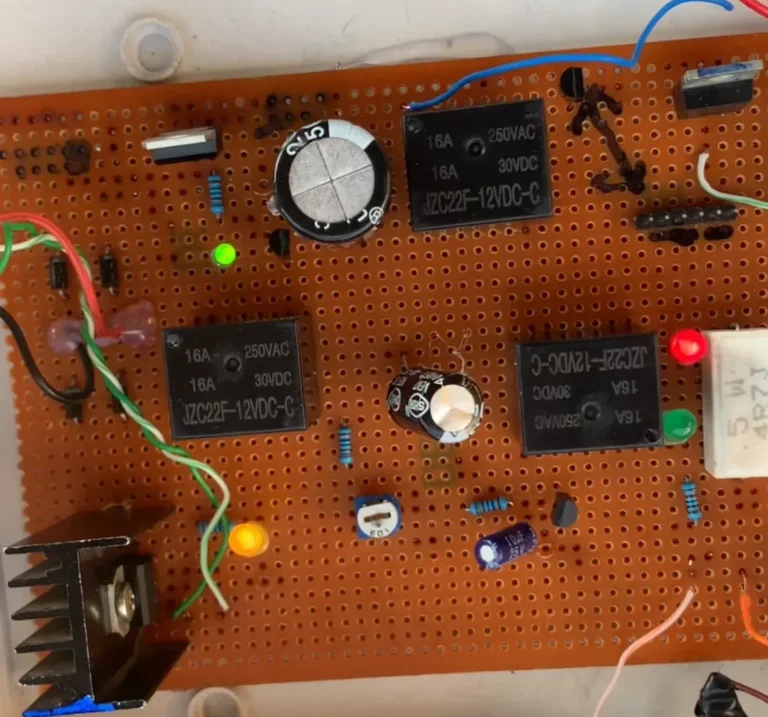
12v dual power source charger images
