Introduction to fire alarm system
One of the most devasting accidents is fire accidents. For home protection, a system must be made available to be able to efficiently detect fire and notify the household of imminent danger. This simple fire alarm system was developed with exactly that in mind. It is very simple to make and is very cost-efficient such that every household can afford one and install it in their houses to alert them of any fire incident before it escalates to an uncontrollable level.
This system just helps in the timely detection of fire occurrence so that the fire is controlled before it escalates to an uncontrollable level. This fire alarm system does not protect from fire incidents.
Electronic components used for this project
| S/No | Component | Rating | Quantity |
| 1 | Battery (Bat1) | 9V | 1 |
| 2 | Potentiometer (Rv1) | 10K | 1 |
| 3 | Resistors (R1,R2,R3,R5) | 1K | 4 |
| 4 | Resistor (R4) | 220 | 1 |
| 5 | Op-Amp LM358 (U1) | – | 1 |
| 6 | Transistor BC547 (T1) | – | 1 |
| 7 | Buzzer (Buz1) | – | 1 |
| 8 | NTC thermistor (RT1) | 20K | 1 |
| 9 | LEDs (D1,D2) | – | 2 |
| 10 | PCB board | – | 1 |
Battery: The battery is used as a voltage source to power this system. A 9V battery is used.
Potentiometer: A potentiometer is a variable resistor that can be manually adjusted. It usually consists of three (3) terminals that are linked to the resistive element of the potentiometer. For better understanding, it is like having two resistors in one. Two (2) terminals of the potentiometer are fixed with one terminal connected to an adjustable knob. A potentiometer has a peak resistance which is the maximum resistance of the potentiometer. To get the values of the resistances in the potentiometer we have to first know the value of one of the resistance and then subtract it from the maximum resistance. For example, if the maximum resistance of the potentiometer is 10K ohms and after adjusting the knob we get 3k ohms to get the value of the other resistor you have to subtract 3k from 10K which will be 7k ohms. For clarity, the two resistors in the potentiometer have the values of 3k ohms and 7K ohms which gives us the value of the potentiometer which is 10K ohms.
Resistors: A resistor is a passive circuit element that limits the flow of current in a circuit.
Op-amp (LM358): Op-amp can be used as an amplifier or as a comparator. For this circuit, we used op-amp as a comparator to compare the voltages at the negative and positive terminals of the op-amp. The output is based on the voltages at the input terminals. If the voltage at the positive terminal is more than that of the negative terminal the output of the comparator will be high. But if the voltage at the negative terminal of the comparator is more than that of the positive terminal the comparator outputs low voltage.

NTC thermistor: Negative temperature coefficient thermistor is a temperature-sensitive resistor that decreases its resistance based on the increase in temperature.
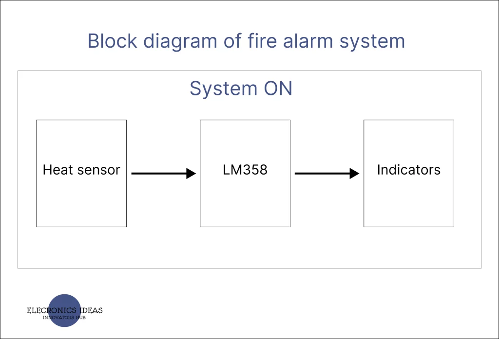
Block diagram of the fire alarm system

Circuit Analysis of the fire alarm system
All the calculations regarding this project are as follows.
IC = collector current
IB = Base current
IE = Emitter current
β = DC = Current gain
RC = collector resistance
RB = Base resistance
IC = 10mA
IE = IB + IC
Given B =100
β = IC/IB
By substitution
IB = IC/ β = 10/100 = 0.1mA
IE = IB + IC = 0.1 + 10 = 10.1mA
But V=IR
RB = V/I = 9/ 10.1 = 0.89k ohms ≈ 1kohm
RC = V/ IC = 9/10 = 0.9k ohm ≈ 1k ohm for red LED
For green LED R4 =V/I = 9/10 = 0.9k ≈ 1k ohm
Vref = V+ = voltage at potentiometer (10k)
Vref=( 8.5/8.5+1.5) VCC
= 8.5/10* VCC = 0.85 * 9 = 7.65V
at room temp of 28°c PTC resistance is 9k ohm. This value decreases on heating
Hence at room temperature V– = 10/10+1*Vcc = RPTC /(R2 + RPTC)*Vcc
V– =9/10*9 =8.1V
Using op-amp as a comparator
Vout = ( V+ -V–) * Av = (7.65 – 8.1)* 1000
=(-0.35)* 1000 ≈ 0 V
NPN transistor will turn on when voltage is high or positive at its base hence at room temperature both buzzer and Red LED are OFF
On heating, the temperature of the PTC begins to rise and resistance begins to get low rapidly. At 45°c resistance of PTC becomes 5k ohms hence
V– = 5/(5+1) = 5/6 = 0.833 * Vcc = 7.499
V– ≈7.5v
Vout = (V+ – V–) * Av
= (7.65-7.5)*1000 = (0.15)* 1000 = 12v
Hence NPN transistor senses the high positive voltage at the base and turns on both Red LED and the buzzer.
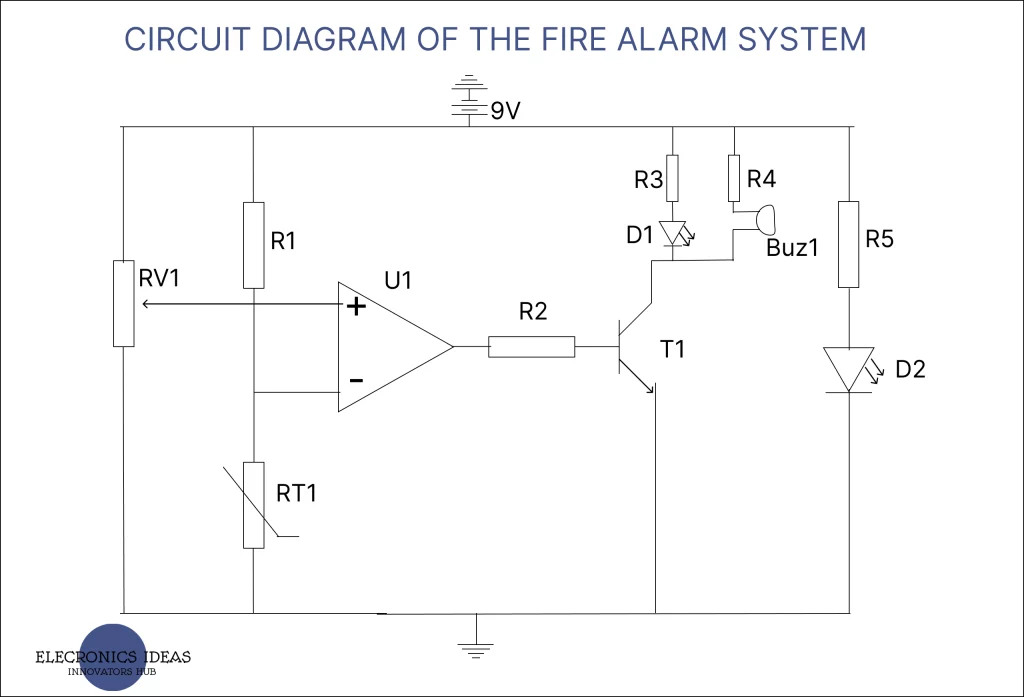
The circuit design of the fire alarm system

Design/ Implementation of design
The above design was implemented on a breadboard to ensure everything works well.


Final work
After all the thorough tests the system was put together on a PCB board and packed properly for better portability.

Work Explanation of the fire alarm system
Once the system is turned ON the operational amplifier continues to compare the voltages at its input terminals. By default, Just one LED (D2) is turned ON to indicate the system is active. The system will not make any sound as the output of the op-amp is low. The buzzer and the LED (D1) become active only when the output of the op-amp is high.
Based on how an NTC thermistor works, an increase in temperature will decrease the resistance of the NTC thermistor toward zero. We will use the voltage divider rule to get the voltages entering each terminal of the comparator.
First for the positive terminal. It is connected to a potentiometer with a rating of 10k ohms, The knob is tuned such that the two resistance gotten are 7k ohms and 3k ohms. Using the voltage divider rule we get 6.3V which is 7×9/10.
NOTE: A potentiometer is used instead of two resistors so that the sensitivity of the system can be adjusted.
Now calculating the voltage at the negative terminal of the comparator. When the NTC thermistor senses heat its resistance drops toward zero. We can take the resistive value of the thermistor to be 500 ohms. Using the voltage divider rule we get 3V. That is 9 x 0.5 /1.5.
Since the voltage at the positive terminal is more than that of the negative terminal, the output of the comparator will be high which will make the transistor acts as a switch connecting the buzzer and the LED (D1) down to ground. Once the transistor allows current to flow down to ground the buzzer starts making an audible sound and the led comes on.
Applications/Uses of the fire alarm system
The system can be used for both domestic and industrial purposes to help alert people before a fire gets out of control.
Conclusion
The system works well as intended and further research can be carried out to change the power source from DC to AC. This will enhance the performance of the system.
Related posts
[wp_show_posts id=”3066″]


Interesting
Love to see more
Thanks for the knowledge
Much appreciated Mr.Trigger