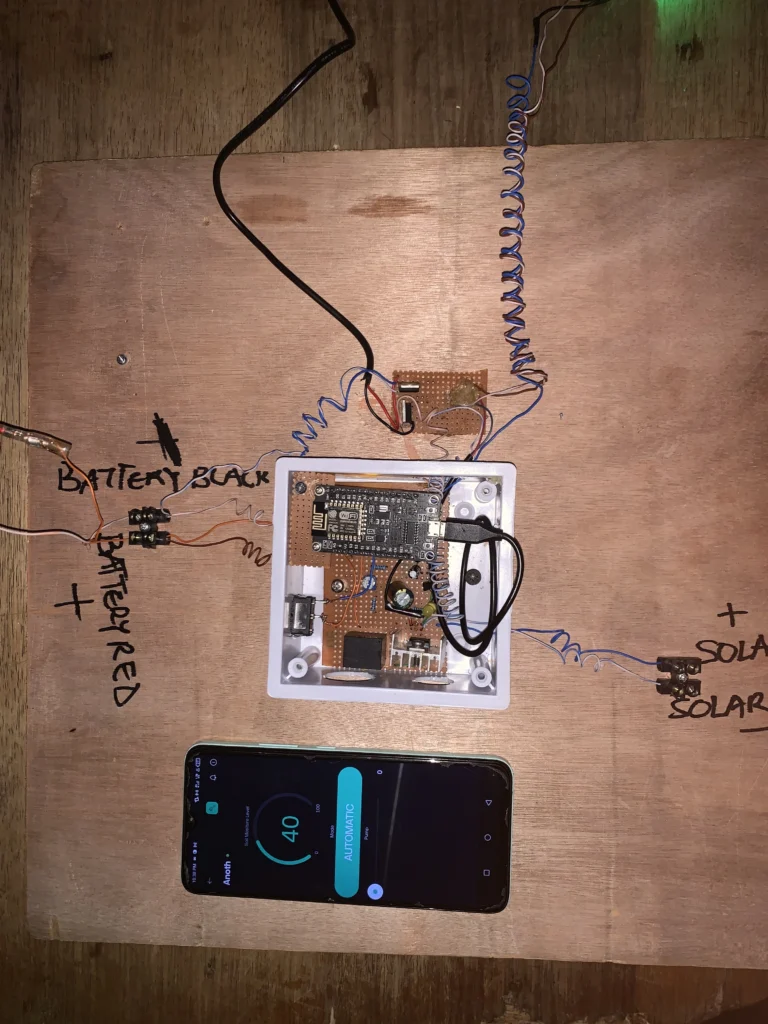
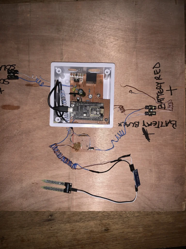
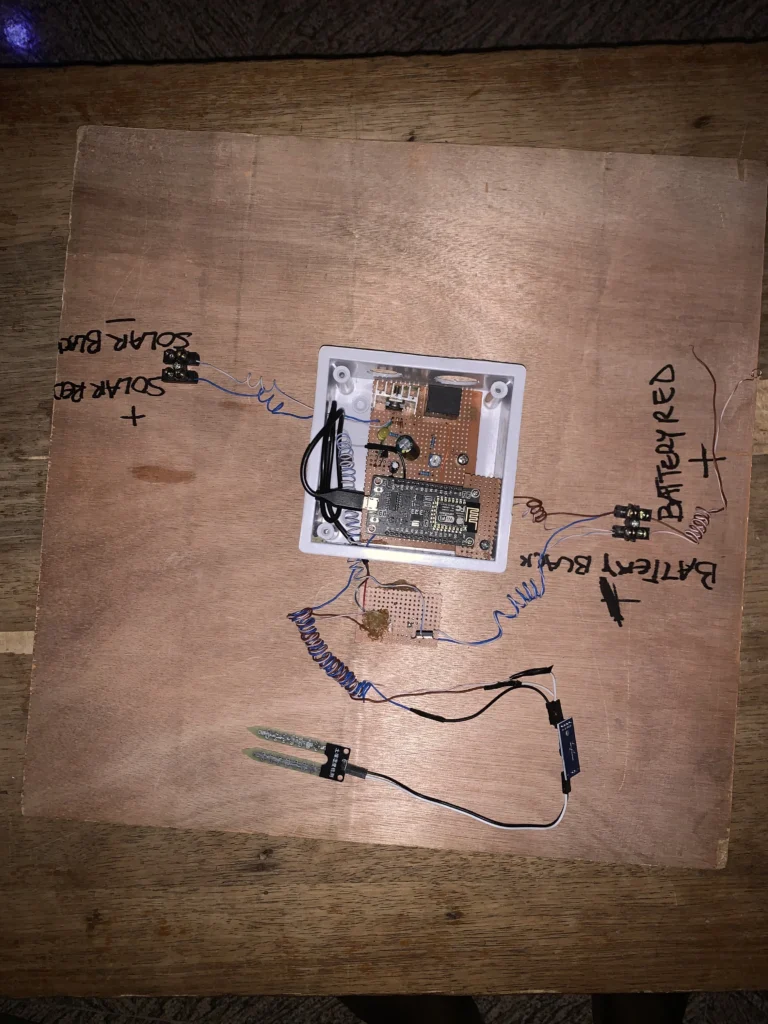
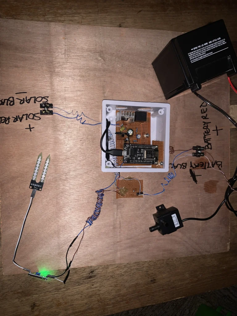
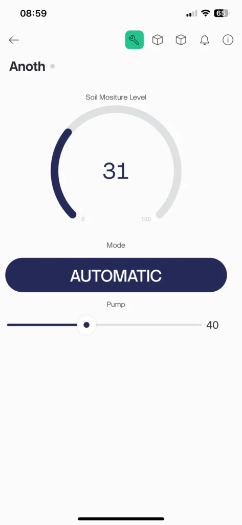
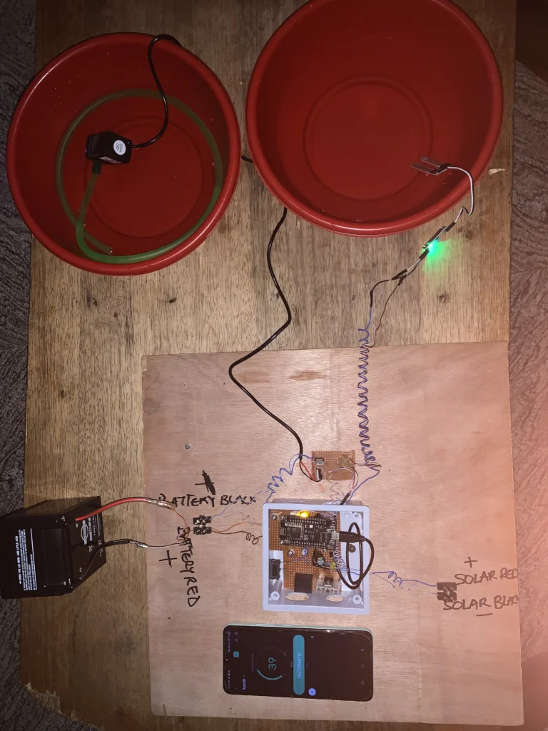
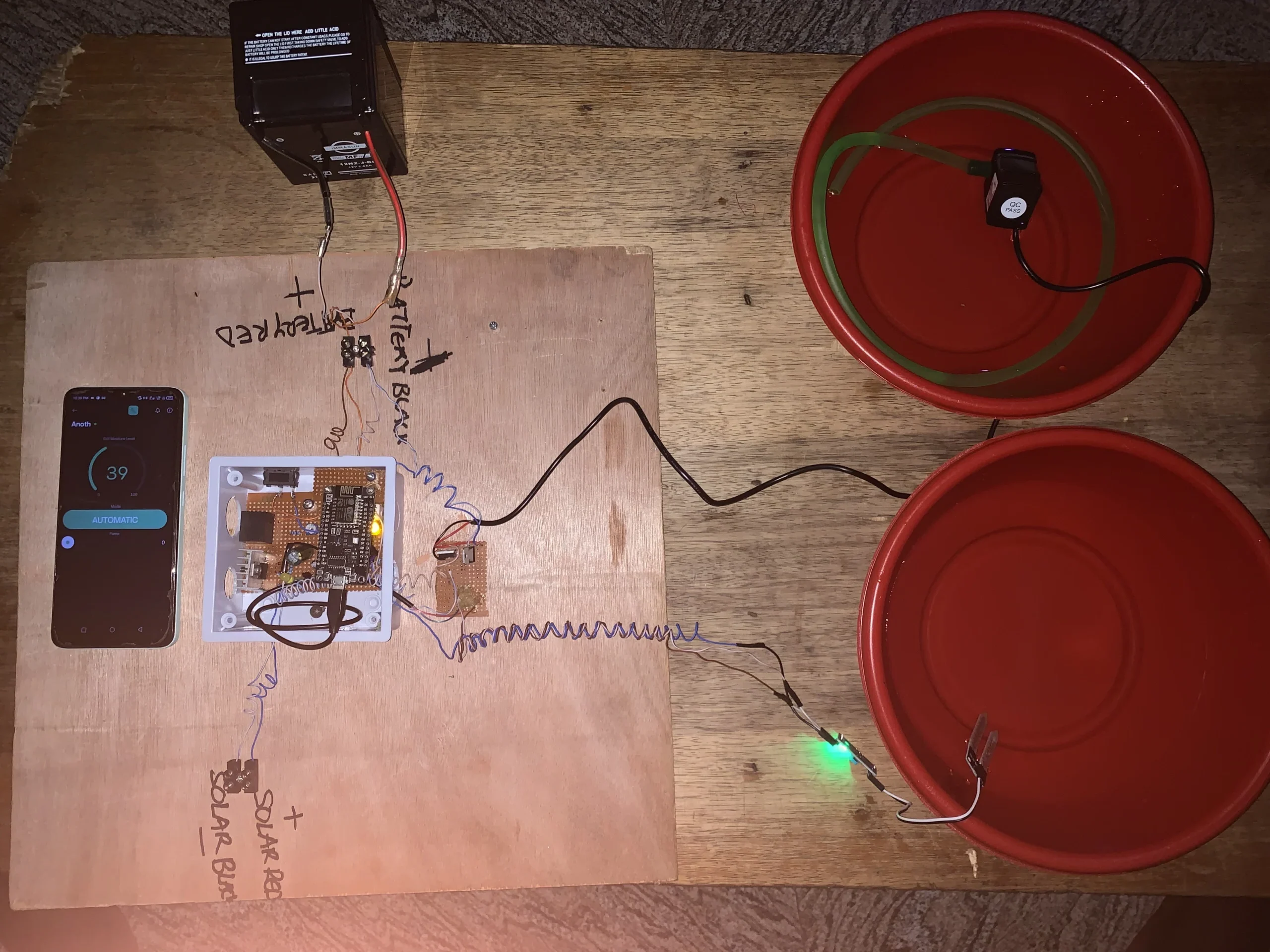
Tradition irrigation systems require farmers to water their crops occasionally at least twice a day. With this design, we intend to make the process automated and also give the farmer the ability to monitor everything remotely from their mobile device.
This irrigation system uses an ESP8266 which features an IoT aspect which connects to the internet wirelessly via WiFi and displays details of the current state of things in real-time via the Blynk IoT.
Components used in this project
| S/NO | Component | Value | QTY |
| 1 | ESP8266 | – | 1 |
| 2 | Soil Moisture Sensor | – | 1 |
| 3 | 12V water Pump | – | 1 |
| 4 | Volatge regulator | 5V | 1 |
| 5 | N-Mosfet | – | 1 |
| 6 | Battery | 12V | 1 |
Circuit Diagram for the Irrigation System
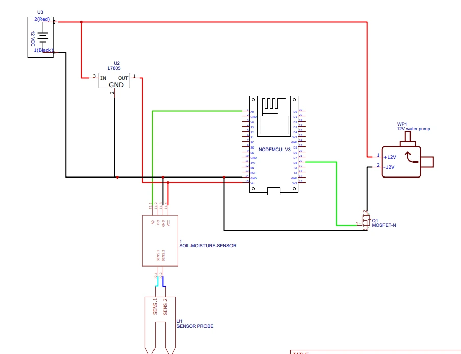
After implementing the circuit, open your Blynk cloud dashboard and create a template, add the device and create the datastreams for the system. You can use these two posts as a guide: Understanding Blynk IOT and Multiple devices on a slave in an I2C system. These posts should give an understanding of how to go about Blynk IoT
Code for the system
#define BLYNK_PRINT Serial

#define BLYNK_TEMPLATE_ID "TMPL21PrvggI0"
#define BLYNK_TEMPLATE_NAME "Chfd"
#define BLYNK_AUTH_TOKEN "_L2bboj-3o65oVX6ueHH_yu3dVJzozpN"

#include <Blynk.h>


#include <ESP8266WiFi.h>
#include <BlynkSimpleEsp8266.h>

char ssid[] = "Infinix SMART 7 HD";
char pass[] = "smart12345";

int soilSensor=A0;
int waterPump=15;
int soilMoistureLevel;
int modeno;
int water;
int reading;
int waterValue;


void setup() {
 pinMode(soilSensor,INPUT);
 pinMode(waterPump,OUTPUT);
 Serial.begin(115200);
 Serial.print("Active");
  WiFi.mode(WIFI_STA);
 WiFi.begin(ssid,pass);
 while(WiFi.status() !=WL_CONNECTED){
  delay(500);
  Serial.print(".");
 }
 Serial.println("Connected");
 Serial.println(ssid);
       Serial.println(WiFi.localIP());

      Serial.println("start Transmission");
      Blynk.begin(BLYNK_AUTH_TOKEN, ssid, pass);
}

BLYNK_WRITE(V1){
 modeno = param.asInt();
   Serial.println(modeno);
}

BLYNK_WRITE(V2){
  water = param.asInt();
  Serial.println(water);
  analogWrite(waterPump,water);
}

void worker(){
  reading=analogRead(soilSensor);
  soilMoistureLevel=map(reading,0,1023,100,0);
  Blynk.virtualWrite(V3,soilMoistureLevel);
  //Serial.println(soilMoistureLevel);
  if (soilMoistureLevel <30){
    analogWrite(waterPump,40);
     Blynk.virtualWrite(V2,40);
  }
  if(soilMoistureLevel>31){
    analogWrite(waterPump,0);
    Blynk.virtualWrite(V2,0);
  }
}

BLYNK_CONNECTED(){
  Blynk.syncVirtual(V1);
  Blynk.syncVirtual(V2);
  Blynk.syncVirtual(V3);
}

void loop() {

  if(modeno==1){
    worker();
   //Serial.println(soilMoistureLevel);
   waterValue=map(reading,0,1023,100,0);
  }
  else if(modeno==0){
  reading=analogRead(soilSensor);
  soilMoistureLevel=map(reading,0,1023,100,0);
  Blynk.virtualWrite(V3,soilMoistureLevel);
  //Serial.println(soilMoistureLevel);
  }
  Blynk.run();
}
I will break down the code for better understanding.
#define BLYNK_TEMPLATE_ID "TMPL21PrvggI0"
#define BLYNK_TEMPLATE_NAME "Chfd"
#define BLYNK_AUTH_TOKEN "_L2bboj-3o65oVX6ueHH_yu3dVJzozpN"
After creating a template in Blynk, you will receive the above details that matches the template you just created in your account. All you have to do is copy the associated details and replace the above code.
char ssid[] = "Infinix SMART 7 HD";
char pass[] = "smart12345";
Replace the SSID and password with your home network’s SSID and password.
void worker(){
  reading=analogRead(soilSensor);
  soilMoistureLevel=map(reading,0,1023,100,0);
  Blynk.virtualWrite(V3,soilMoistureLevel);
  //Serial.println(soilMoistureLevel);
  if (soilMoistureLevel <30){
    analogWrite(waterPump,40);
     Blynk.virtualWrite(V2,40);
  }
  if(soilMoistureLevel>31){
    analogWrite(waterPump,0);
    Blynk.virtualWrite(V2,0);
  }
}
This function controls the system automatically. It tells the system to allow water flow if the soil moisture level is below 30%. AnalogWrite is used to control the amount of flow. You can use digitalwrite, this allows the pump to work at full speed. The VirtualWrite function updates the soil’s water level in real-time on the Blynk app.
BLYNK_CONNECTED(){
  Blynk.syncVirtual(V1);
  Blynk.syncVirtual(V2);
  Blynk.syncVirtual(V3);
}
This piece of code syncs the system to function as one always. You can have multiple users that will see any adjustments to any part of the system.
 if(modeno==1){
    worker();
   //Serial.println(soilMoistureLevel);
   waterValue=map(reading,0,1023,100,0);
  }
  else if(modeno==0){
  reading=analogRead(soilSensor);
  soilMoistureLevel=map(reading,0,1023,100,0);
  Blynk.virtualWrite(V3,soilMoistureLevel);
  //Serial.println(soilMoistureLevel);
  }
This code details the function of each mode of the system. In manual mode, the slider widgets control the system remotely.
