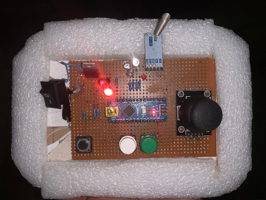
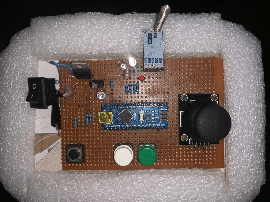
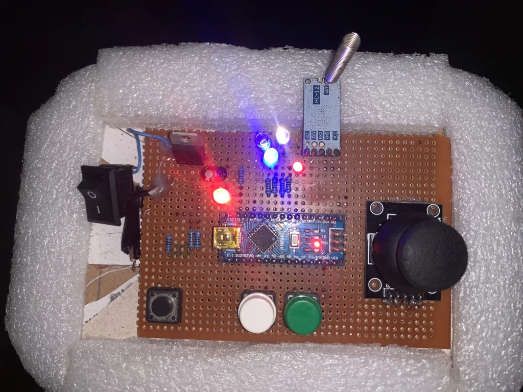
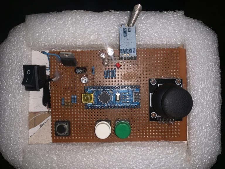
We developed a 2 Channel HC12 module wireless remote in this project. This remote will be able to send commands to 2 different HC12 receivers operating on different channels.
We will make use of Arduino boards and HC12 antenna. Arduino Nano was used on the remote any Arduino will work just fine.
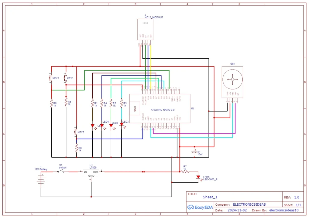
Components Used for this project
| S/NO | Component | Value | QTY |
| 1 | Nano | – | 1 |
| 2 | HC12 | – | 1 |
| 3 | Joystick | – | 1 |
| 4 | L7805 | 5v | 1 |
| 5 | Capacitor | 10uf | 1 |
| 6 | Pushbuttons | – | 3 |
| 7 | Resistors | 1K | 7 |
| 8 | LEDs | – | 5 |
Circuit Diagram for 2 Channel HC12 module wireless remote
2 Channel HC12 module wireless remote code
#include <SoftwareSerial.h>

SoftwareSerial HC12(10, 11);

int xAxis = A0;
int yAxis = A1;
int power = 2;
int connectionLed = 4;
int powerLed = 5;
int channelOneLed = 6;
int channelTwoLed = 7;
int setPin = 9;
int channelOne = 12;
int channelTwo = 13;
int ledSelector;

byte incomingByte;
String readBuffer = "";

int button1State = 0;
int button1Pressed = 0;
int button2State = 0;
int button2Pressed = 0;

int powerledState;
int powerState;
int modeTake;

int xValue=512;
int yValue=512;

int xAxismap ;
int yAxismap;

int output[3];


void setup() {
  Serial.begin(9600);
  HC12.begin(9600);
 // pinMode(xAxis, INPUT);
 // pinMode(yAxis, INPUT);
  pinMode(power, INPUT);
  pinMode(connectionLed, OUTPUT);
  pinMode(powerLed, OUTPUT);
  pinMode(channelOneLed, OUTPUT);
  pinMode(channelTwoLed, OUTPUT);
  pinMode(setPin, OUTPUT);
  pinMode(channelOne, INPUT);
  pinMode(channelTwo, INPUT);
  digitalWrite(setPin, HIGH);

}

void switcher() {
  powerledState = digitalRead(powerLed);
  powerState = digitalRead(power);
  delay(500);
  if (powerledState == 0) {
    if (powerState == 1) {
      modeTake = 1;
      digitalWrite(powerLed, HIGH);
    }
  }
  else if (powerledState == 1) {
    if (powerState == 1) {
      modeTake = 0;
      digitalWrite(powerLed, LOW);
    }
  }

  switch (modeTake) {
    case 0:
      digitalWrite(powerLed, LOW);
      powerledState = 0;
      break;
    case 1:
      digitalWrite(powerLed, HIGH);
      powerledState = 1;
      break;
    default:
      digitalWrite(powerLed, LOW);
      powerledState = 0;
      break;

  }
}


void loop() {
  switcher();

  xValue = analogRead(xAxis);
  yValue = analogRead(yAxis);
  xAxismap=map(xValue,0,1023,0,100);
  yAxismap=map(yValue,0,1023,0,180);

  for (int i = 0; i < 3; i++) {
    HC12.write(output[i]);
    Serial.print(output[i]);
    Serial.print("\t");
  }
  Serial.println();
  readDistance();

  while (HC12.available()) {
    incomingByte = HC12.read();
    readBuffer += char(incomingByte);
    digitalWrite(connectionLed, HIGH);
  }
  delay(100);
  while (Serial.available()) {
    HC12.write(Serial.read());
  }

  button1State = digitalRead(channelOne);
  if (button1State == HIGH & button1Pressed == LOW) {
    button1Pressed = HIGH;
    delay(20);
  }
  if (button1Pressed == HIGH) {
    HC12.print("AT+C001");
    delay(100);
    digitalWrite(setPin, LOW);
    delay(100);
    HC12.print("AT+C001");
    delay(200);
    while (HC12.available()) {
      Serial.write(HC12.read());
    }
    Serial.println("Channel successfully changed");
    ledSelector = 1;
    digitalWrite(setPin, HIGH);
    button1Pressed = LOW;
  }

  button2State = digitalRead(channelTwo);
  if (button2State == HIGH & button2Pressed == LOW) {
    button2Pressed = HIGH;
    delay(100);
  }
  if (button2Pressed == HIGH) {
    HC12.print("AT+C002");
    delay(100);
    digitalWrite(setPin, LOW);
    delay(100);
    HC12.print("AT+C002");
    delay(200);
    while (HC12.available()) {
      digitalWrite(connectionLed, HIGH);
      Serial.write(HC12.read());
    }
    Serial.println("Channe2 successfully changed");
    ledSelector = 2;
    digitalWrite(setPin, HIGH);
    button2Pressed = LOW;
  }

  checkATCommand();
  readBuffer = "";
  switch (ledSelector) {
    case 1:
      one();
      break;
    case 2:
      two();
      break;
  }
}

void checkATCommand () {
  while (readBuffer.startsWith("AT")) {
    digitalWrite(setPin, LOW);
    delay(200);
    HC12.print(readBuffer);
    delay(200);
    while (HC12.available()) {
      digitalWrite(connectionLed, HIGH);
      Serial.write(HC12.read());
    }
    digitalWrite(setPin, HIGH);
  }
}

void one() {
  digitalWrite(channelOneLed, HIGH);
  digitalWrite(channelTwoLed, LOW);
}

void two() {
  digitalWrite(channelOneLed, LOW);
  digitalWrite(channelTwoLed, HIGH);
}

void readDistance() {
  output[0] = xAxismap;
  delay(100);
  output[1] = yAxismap;
  delay(100);
  output[2] = powerledState;
  delay(100);
}
Code Explanation for 2 Channel HC12 module wireless remote
#include <SoftwareSerial.h>

SoftwareSerial HC12(10, 11);
The HC12 module makes use of serial communication. The SoftwareSerial library creates a separate serial communication bus. We named our new serial line and assigned RX and TX pins. 10 is rx and 11 is tx.
int xAxis = A0;
int yAxis = A1;
int power = 2;
int connectionLed = 4;
int powerLed = 5;
int channelOneLed = 6;
int channelTwoLed = 7;
int setPin = 9;
int channelOne = 12;
int channelTwo = 13;
int ledSelector;

byte incomingByte;
String readBuffer = "";

int button1State = 0;
int button1Pressed = 0;
int button2State = 0;
int button2Pressed = 0;

int powerledState;
int powerState;
int modeTake;

int xValue=512;
int yValue=512;

int xAxismap ;
int yAxismap;

int output[3];
The above section is just for variable declaration.
  Serial.begin(9600);
  HC12.begin(9600);
In the void setup(), we initialize both the hardwareSerial and the softwareSerial using the above lines.
void switcher() {
  powerledState = digitalRead(powerLed);
  powerState = digitalRead(power);
  delay(500);
  if (powerledState == 0) {
    if (powerState == 1) {
      modeTake = 1;
      digitalWrite(powerLed, HIGH);
    }
  }
  else if (powerledState == 1) {
    if (powerState == 1) {
      modeTake = 0;
      digitalWrite(powerLed, LOW);
    }
  }

  switch (modeTake) {
    case 0:
      digitalWrite(powerLed, LOW);
      powerledState = 0;
      break;
    case 1:
      digitalWrite(powerLed, HIGH);
      powerledState = 1;
      break;
    default:
      digitalWrite(powerLed, LOW);
      powerledState = 0;
      break;

  }
}
This function makes a pushbutton act like an SPST switch. It simply checks the state of the LED every half a second. when the pushbutton is pressed for half a second the code checks the state of the switch and either turns the LED on or off.
void readDistance() {
  output[0] = xAxismap;
  delay(100);
  output[1] = yAxismap;
  delay(100);
  output[2] = powerledState;
  delay(100);
}

 for (int i = 0; i < 3; i++) {
    HC12.write(output[i]);
    Serial.print(output[i]);
    Serial.print("\t");
  }
  Serial.println();
  readDistance();
This code sends the commands (the joystick readings and the button state) to the receiver as a single byte.
xValue = analogRead(xAxis);
  yValue = analogRead(yAxis);
  xAxismap=map(xValue,0,1023,0,100);
  yAxismap=map(yValue,0,1023,0,180);
Given that a byte is 255 maximum, we use the map function to adjust the joystick readings to fall below 255. If you try to send a value greater than 255 the receiver will get the wrong values.
while (HC12.available()) {
    incomingByte = HC12.read();
    readBuffer += char(incomingByte);
    digitalWrite(connectionLed, HIGH);
  }
  delay(100);
  while (Serial.available()) {
    HC12.write(Serial.read());
  }

  button1State = digitalRead(channelOne);
  if (button1State == HIGH & button1Pressed == LOW) {
    button1Pressed = HIGH;
    delay(20);
  }
  if (button1Pressed == HIGH) {
    HC12.print("AT+C001");
    delay(100);
    digitalWrite(setPin, LOW);
    delay(100);
    HC12.print("AT+C001");
    delay(200);
    while (HC12.available()) {
      Serial.write(HC12.read());
    }
    Serial.println("Channel successfully changed");
    ledSelector = 1;
    digitalWrite(setPin, HIGH);
    button1Pressed = LOW;
  }

  button2State = digitalRead(channelTwo);
  if (button2State == HIGH & button2Pressed == LOW) {
    button2Pressed = HIGH;
    delay(100);
  }
  if (button2Pressed == HIGH) {
    HC12.print("AT+C002");
    delay(100);
    digitalWrite(setPin, LOW);
    delay(100);
    HC12.print("AT+C002");
    delay(200);
    while (HC12.available()) {
      digitalWrite(connectionLed, HIGH);
      Serial.write(HC12.read());
    }
    Serial.println("Channe2 successfully changed");
    ledSelector = 2;
    digitalWrite(setPin, HIGH);
    button2Pressed = LOW;
  }


void checkATCommand () {
  while (readBuffer.startsWith("AT")) {
    digitalWrite(setPin, LOW);
    delay(200);
    HC12.print(readBuffer);
    delay(200);
    while (HC12.available()) {
      digitalWrite(connectionLed, HIGH);
      Serial.write(HC12.read());
    }
    digitalWrite(setPin, HIGH);
  }
}
The above code changes the channel of the transmitter using AT commands. In this project, we have two channels C001 and C002.
Explanation of operation of 2 Channel HC12 module wireless remote
The 2 Channel HC12 module wireless remote is designed with two control points: a joystick and a pushbutton. The Joystick can control a ranged device such as a servo motor or an ESC. The push button acts like a normal SPST switch, but it must be pressed for half a second to pick the state. It can also be used to turn on and off a Device or an LED.
Project images for 2 Channel HC12 module wireless remote
